Fibre-optical prefabricated bar processing apparatus by plasma technology

A technology of optical fiber preform and plasma, which is applied in glass manufacturing equipment, manufacturing tools, optics, etc., can solve problems such as difficult heat dissipation and complex adjustment, and achieve good results and enhanced cooling and shielding effects

Inactive Publication Date: 2005-02-09
FENGHUO COMM SCI & TECH CO LTD
View PDF3 Cites 0 Cited by
  • Summary
  • Abstract
  • Description
  • Claims
  • Application Information

AI Technical Summary

Problems solved by technology

[0004] The existing plasma optical fiber preform processing equipment has the following disadvantages: firstly, the matching of the adjusting cavity and the matching of the adjusting converter affect each other; secondly, since the resonating cavity works at high temperature, both the resonating cavity and the outer conductor of the coaxial line can be used Water cooling, and the inner conductor of the coaxial line is a suspended structure, which makes it difficult to dissipate heat; third, the adjustment is complicated. In order to improve the above two shortcomings, the patent also adds a device for adjusting the short-circuit surface of the waveguide (not shown in the figure)

Method used


Image

  • Fibre-optical prefabricated bar processing apparatus by plasma technology
  • Fibre-optical prefabricated bar processing apparatus by plasma technology
  • Fibre-optical prefabricated bar processing apparatus by plasma technology

Examples


Embodiment Construction

[0014] The present invention will be explained in detail below in conjunction with specific embodiments.

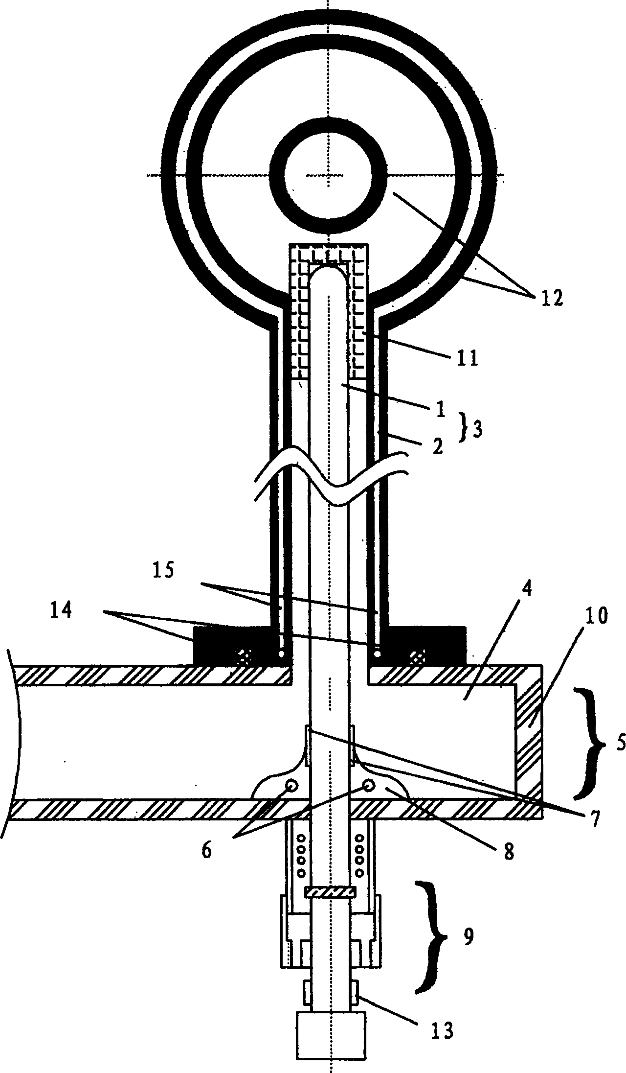
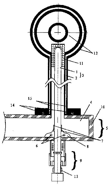
[0015] Such as figure 2 As shown, the embodiment of the optical fiber preform processing equipment of the present invention is composed of several parts: a cylindrical coaxial resonant cavity 12; a waveguide 4 on a short-circuit surface 10; a coaxial line 3 (including an inner conductor 1 and an outer conductor 2); There is a door button type structure 8 of claw-shaped axle sleeve 7; a lifting structure 9 with a lifting counter 13 and additional devices (comprising water cooling pipes 6, 15, anti-leakage device 14 and support member fasteners, etc.).

[0016] The door button structure is welded in the middle of the wide side of the waveguide, and the waveguide model is BJ-22 (size 109.2*54.6mm) or BJ-26 (size 86.4*43.2mm). The position of the short-circuit surface is determined by experiments and welded on the waveguide. Since the inner conductor of the coaxial line is...


PUM


Abstract

An equipment for preparing the prefabricated optical-fibre rod by plasma technique is composed of plasma resonance cavity, coaxial line and rectangular microwave waveguide. A microwave energy transmission converter with doorknob contact type coaxial waveguide conversion structure is also used, which features reliable contact during regulation and good heat dissipation. The water cooling and anti-leakage apparatus is also designed.

Description

technical field [0001] The invention relates to an optical fiber preform processing equipment using plasma technology, in particular to the improvement of the microwave energy transmission conversion device in the equipment. Background technique [0002] In the PCVD optical fiber preform manufacturing system, the microwave plasma system is the core key equipment for chemical vapor deposition. Microwave energy is usually generated by a continuous wave magnetron with a frequency of 2450MHz and a power of several thousand watts. The magnetron first excites the microwave energy in the rectangular hollow waveguide, and then transmits it to the plasma reactor. Plasma reactors usually employ resonant cavities. The resonant cavity is usually used to couple microwave energy inductively or capacitively. This requires a coaxial connection. Therefore, there must be a microwave energy transmission conversion device from the rectangular hollow waveguide to the coaxial line. [0003] ...

Claims


Application Information

Patent Timeline
Patent Type & Authority Patents(China)
IPC IPC(8): C03B37/018C23C16/50C23C16/513G02B6/00
Inventor 邓都才刘志坚
Owner FENGHUO COMM SCI & TECH CO LTD
Why Eureka
Try Eureka