Nonreciprocal circuit device and its mounting structure

A technology of circuit devices and circuit boards, applied in the direction of circuits, electrical components, waveguide devices, etc., can solve the problems of miniaturization and weight reduction, difficulty in miniaturization of devices, loss, etc.

Inactive Publication Date: 2005-02-23
MURATA MFG CO LTD
View PDF0 Cites 0 Cited by
  • Summary
  • Abstract
  • Description
  • Claims
  • Application Information

AI Technical Summary

Problems solved by technology

[0010] 3) Even when the connection pattern is designed to have the best matching, various losses (losses) will still occur, such as loss due to radiation from the conductor pattern, dielectric loss of the printed circuit board, conductor of the conductor pattern loss, and loss due to reflections in parts of the imperfect match
[0011] 4) The connection pattern is set on the printed circuit board between the isolator and the front-stage circuit, and it needs to occupy a certain area for this position, so that this position becomes a dead point, which brings great advantages to the miniaturization of the entire device. Difficulty
[0013] 5) The printed circuit board needs to have an opening to fit the isolator, so unless the opening is simply configured, a mold is required, which increases the cost
[0014] 6) The ground block for connecting the ground conductor on the bottom surface of the isolator needs to be provided at the bottom of the opening of the printed circuit board for mounting the isolator, so that miniaturization and lightening of the entire equipment such as communication equipment Difficulty with weight

Method used


Image

  • Nonreciprocal circuit device and its mounting structure
  • Nonreciprocal circuit device and its mounting structure
  • Nonreciprocal circuit device and its mounting structure

Examples


Embodiment Construction

[0044] 1A to 5B, the isolator and its mounting structure according to the first embodiment will be described.

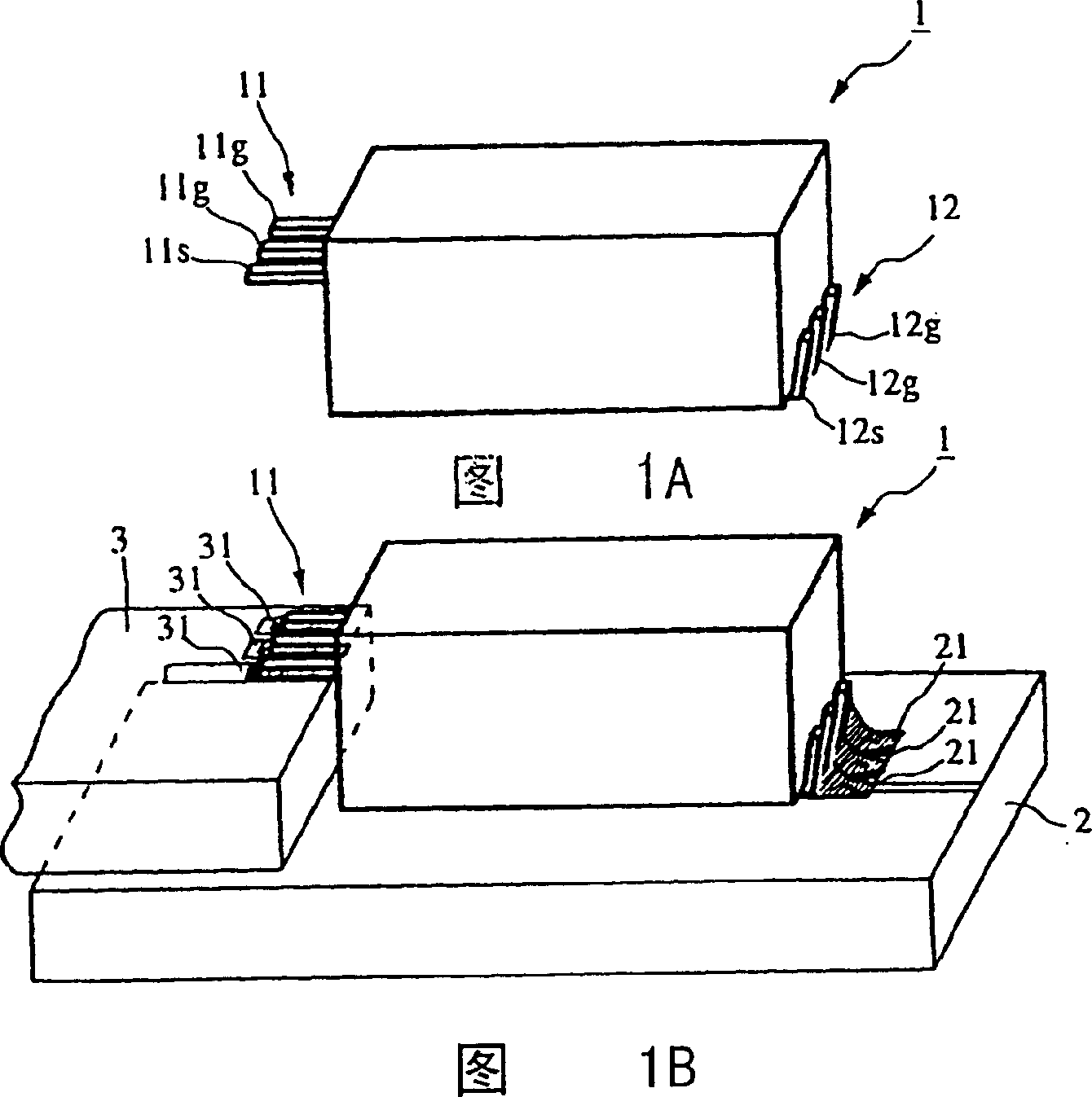
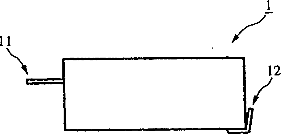
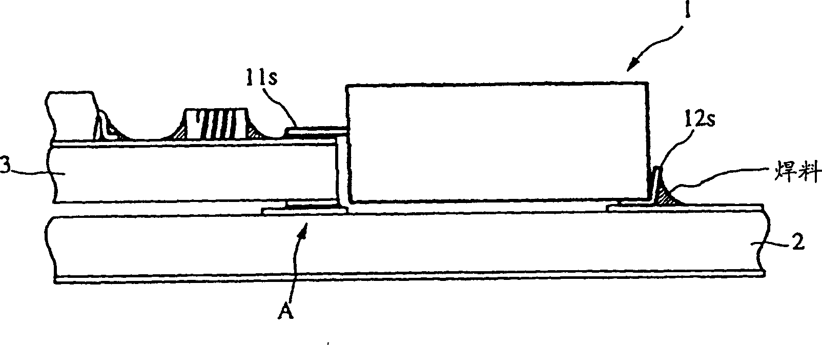
[0045] Fig. 1A is a perspective view of an isolator; Fig. 1B is a perspective view of the isolator in an installed state. The bottom surface of the isolator 1 seen in the figure is a mounting surface; the input terminals 11 are arranged in parallel on the first side of the mounting surface and are at a predetermined height; the output terminals 12 are arranged in parallel on the installation opposite to the first side. The second side of the surface. The input terminal 11 is formed by a hot (voltage) terminal 11s and two ground terminals 11g; the output terminal 12 is formed by a hot terminal 12s and two ground terminals 12g.

[0046] In FIG. 1B, a module circuit board 3 and an isolator 1 are mounted on the top surface of a printed circuit board 2, which forms most of the circuits of the communication device. On the module circuit board 3, for example, a power amplifier ...


PUM


Abstract

In order to suppress losses, unnecessary radiation, and internal mutual interference produced in a connecting portion between a nonreciprocal circuit device and circuits to be connected thereto and to promote reduction in size and weight of the device, a nonreciprocal circuit device and its mounting structure are provided. Output terminals are disposed on a mounting surface (bottom surface) of an isolator and input terminals are disposed at a height higher from the bottom surface as much as the height of a module circuit board. The top surface of the module circuit board is provided with connecting pads for connecting to the input terminals of the isolator. The module circuit board is provided with a shield case which is connected to ground terminals protruding from a yoke of the isolator. A part in which the module circuit board is integrated with the isolator is mounted on a printed circuit board.

Description

Technical field [0001] The present invention relates to non-reversible (unidirectional) circuit devices, such as isolators and circulators for microwave frequency bands, and to a mounting structure of such non-reciprocal circuit devices and communication equipment having such non-reciprocal circuit devices. Background technique [0002] Heretofore, the lumped constant type isolator includes, for example: a ferrite assembly, which has a plate-shaped ferrite, in which a plurality of central conductors are arranged close to each other and cross each other; a magnet, which is housed in a housing and used for feeding The ferrite board applies a static magnetic field; and input / output terminals, which are exposed or protruded outside the housing. [0003] FIGS. 13A to 15B show a method for leading input / output terminals from the housing of such a conventional isolator, and show a structure for mounting the isolator on a substrate of a communication device or the like. [0004] Fig. 13A...

Claims


Application Information

Patent Timeline
Patent Type & Authority Patents(China)
IPC IPC(8): H01P1/36H01P1/32H01P1/383H01P1/387
CPCH01P1/387H01P1/32
Inventor 川浪崇
Owner MURATA MFG CO LTD
Why Eureka
Try Eureka