Electric connertor module with guide pin locking system

An electrical connector and connector technology, which is applied to the parts, connections, electrical components and other directions of the connecting device, and can solve problems such as requiring space or occupying connectors.

Inactive Publication Date: 2005-02-23
MOLEX INC
View PDF0 Cites 0 Cited by
  • Summary
  • Abstract
  • Description
  • Claims
  • Application Information

AI Technical Summary

Problems solved by technology

Here too, such a guide mechanism requires spa

Method used


Image

  • Electric connertor module with guide pin locking system
  • Electric connertor module with guide pin locking system
  • Electric connertor module with guide pin locking system

Examples


Embodiment Construction

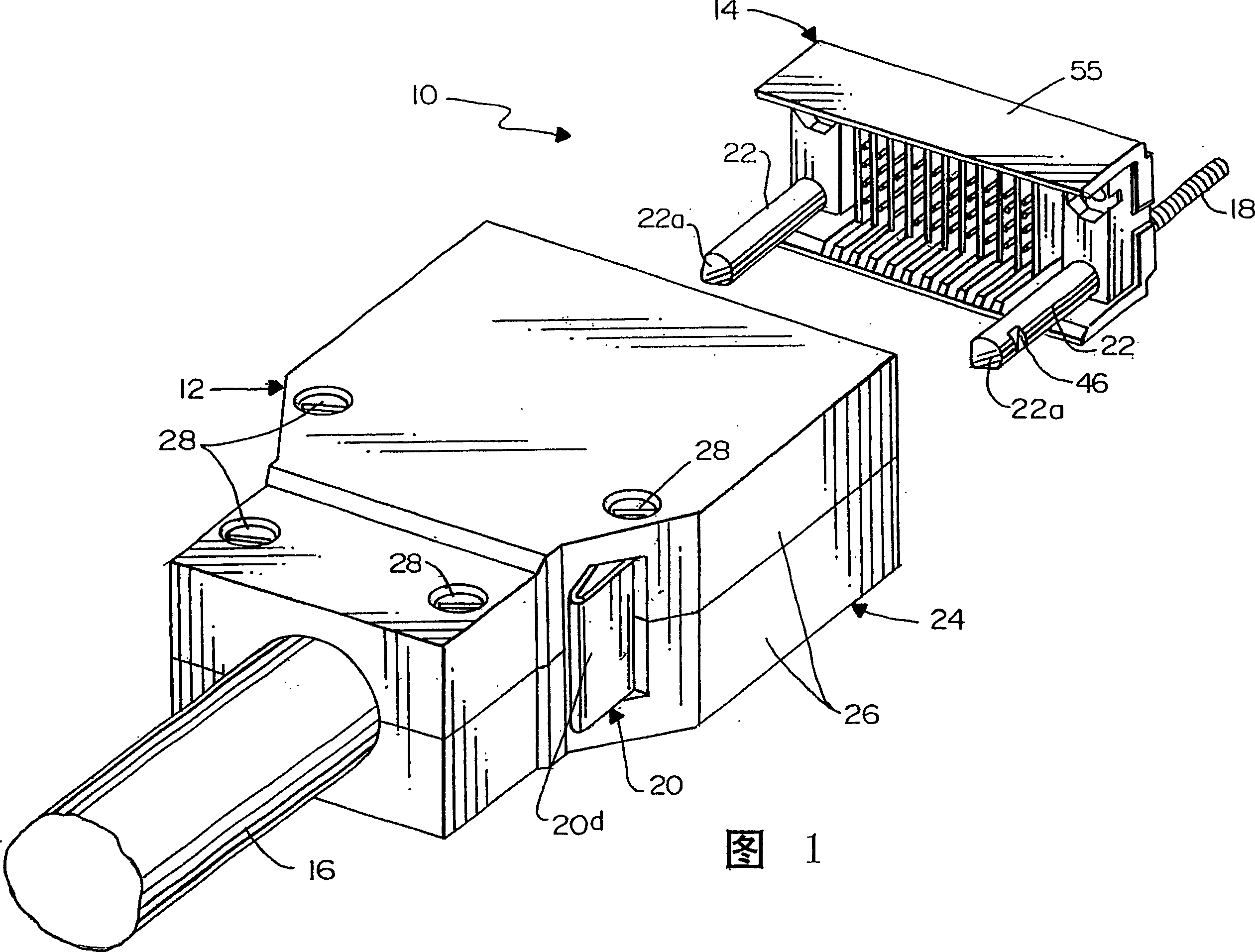
[0015] Referring to the drawings in more detail and turning first to FIG. 1 , an electrical connector assembly generally indicated at 10 embodies the present invention and includes a first connector or cable connector generally indicated at 12 and a first connector generally indicated at 14 . Second connector or header connector. The cable connector 12 is used to terminate multiple pairs of conductors of a high speed cable 16 . The header connector 14 includes a pair of externally threaded mounting posts 18 for mounting the header connector to a chassis, panel, or the like. As will be seen in greater detail hereinafter, the cable connector 12 mounts on opposite sides a pair of latch members 20 which operatively engage a pair of guide pins 22 at the ends of the header connector 14 .

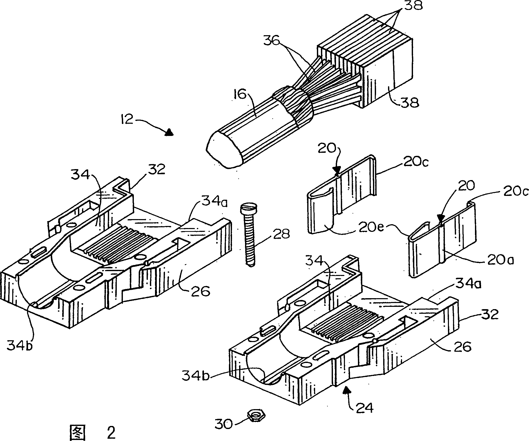
[0016] Referring to Figures 2 and 3 in conjunction with Figure 1, the cable connector 12 includes a housing generally indicated at 24 which is formed by securing together a pair of substantially ...


PUM


Abstract

An electrical connector assembly (10) includes a first connector (12) having a guide hole (50) in a mating face (32) thereof. A second connector (14) includes a guide pin (22) for insertion into the guide hole of the first connector, the guide pin having a latch portion (46). A latch member (20) on the first connector (12) engages the latch portion (46) of the guide pin (22) of the second connector (14) when the connectors are mated to hold the connectors in mated condition. Therefore, the guide pin (22) performs a dual function of guiding the connectors (12,14) as well as latching the connectors.

Description

technical field [0001] The present invention generally relates to electrical connector technology, and more particularly relates to an electrical connector assembly including a guide pin, the guide pin has the function of guiding a pair of connectors to form a mated state and locking the connectors Dual function in mated state. Background technique [0002] A typical electrical connector assembly includes a pair of electrical connectors that interconnect respective conductive terminals when the pair is mated. In some assemblies, an additional locking mechanism is provided to keep the connectors in a mated state and prevent the connectors from being separated. Obviously, such a locking mechanism requires space or occupies part of the area of ​​the connector. In some cases, this space is very large compared to the very small terminals of the connector. If the connector is mounted on a circuit board, panel or the like, the space required for the latch mechanism may take up v...

Claims


Application Information

Patent Timeline
IPC IPC(8): H01R13/639H01R13/436H01R13/627H01R13/629H01R13/631
CPCH01R13/6275Y10S439/953H01R13/629H01R13/436
Inventor M·J·米斯金M·F·马加尼
Owner MOLEX INC
Why Eureka
Try Eureka