In-situ repair structure for municipal household waste landfill and method thereof

A technology for in-situ restoration of municipal solid waste, applied in the structural field of in-situ restoration of municipal solid waste landfills, can solve problems such as high moisture content, palliative treatment but not root cause, stale waste that cannot fully meet the incineration standards, etc.

Inactive Publication Date: 2018-11-20
贵州富燃环保科技有限公司
View PDF3 Cites 0 Cited by
  • Summary
  • Abstract
  • Description
  • Claims
  • Application Information

AI Technical Summary

Problems solved by technology

However, stabilization and ecological restoration are only treatment of the surface of the landfill, and a large amount of garbage still exists in the form of accumulation. The continuous discharge of leachate and the overflow of landfill gas require a large amount of maintenance work in the later stage.
The existing treatment method is to treat the symptoms but not the root cause. The landfill is like a big cancer, which still has a continuous adverse impact on the environment.
[0005] It is difficult to dispose of stale waste in landfills well by adopting foreign introduction and domestic current incineration technology
Because the garbage filled in the landfill is directly exposed on the ground, the old garbage has complex components and high moisture content, and it is piled up all the year round, which leads to the degradation of organic matter in the garbage, resulting in a decrease in the content of combustibles and an extremely low overall calorific value. Stale waste cannot fully meet the standards of existing incineration technology for incineration of waste into furnaces
In view of the fact that the current waste incineration technology and landfill in-situ restoration technology cannot completely carry out environmentally friendly disposal of stale waste in urban landfills, the site restoration of urban landfills has become an environmental problem facing our country

Method used


Image

  • In-situ repair structure for municipal household waste landfill and method thereof

Examples


Embodiment 1

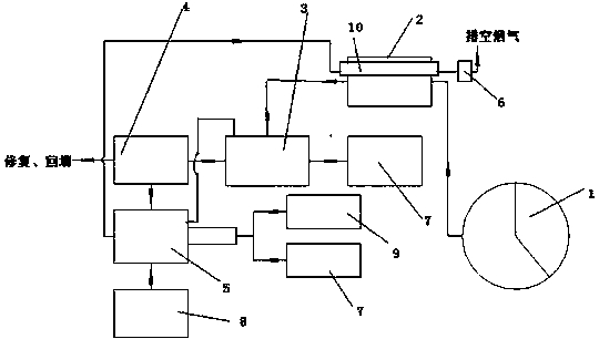
[0023] Example 1. If figure 1 As shown, a structure for in-situ restoration of a municipal solid waste landfill, which includes a screening device 1, the screening device 1 is connected to the garbage preheating furnace 2 through the feeding device I, and the garbage preheating furnace 2 is equipped with a replacement The heating device 10, the garbage preheating furnace 2 is connected with the layer combustion incineration equipment 3 through the feeding device II, and the layer combustion incineration equipment 3 is a mechanical grate furnace, a rotary kiln or a layer combustion pyrolysis furnace, and on the layer combustion incineration equipment 3 An air distribution system 7 is provided; a smoke outlet and a slag outlet are provided on the layer combustion incineration equipment 3, and the slag outlet is connected with the slag screening device 4, and the smoke outlet and the slag screening device 4 are connected to the secondary Combustion furnace 5 is connected, is prov...


PUM


Abstract

The invention discloses an in-situ repair structure for a municipal household waste landfill and a method thereof. The structure comprises a screening device (1) which is connected to a waste preheating furnace (2) through a feeding device I; a heat exchange device (10) is arranged on the waste preheating furnace (2); the waste preheating furnace (2) is connected to a grate-fired incineration device (3) through a feeding device II; a smoke outlet and a slag outlet are formed in the grate-fired incineration device (3); the slag outlet is connected to a slag screening device (4); the smoke outlet and the slag screening device (4) are connected to a secondary combustion furnace (5); a pipeline connected to a heat exchange device (10) is arranged on the secondary combustion furnace (5); the heat exchange device (10) is connected to a flue gas treatment device (6); and the flue gas treatment device (6) is arranged on the waste preheating furnace (2). The structure provided by the inventioncan be used for treating accumulated waste, reducing the occupied space of the waste and reducing the damage of the landfill on soil and water sources, so that the secondary pollution on the environment is avoided effectively.

Description

technical field [0001] The invention relates to a structure and a method for in-situ restoration of a municipal domestic garbage landfill, and belongs to the technical field of garbage dump disposal. Background technique [0002] Sanitary landfill of domestic waste is the main way to deal with urban domestic waste in my country at present, accounting for about 80% of the total waste. However, with the rapid development of cities in our country, there are obvious problems in the operation and closure of waste landfills, especially the impact of landfills on the environment: the odor and dust emitted by landfills affect the environment around the landfill. The surface atmosphere causes serious pollution; landfill leachate contains high concentrations of organic matter and various heavy metals, especially a large amount of carcinogens, which can easily cause large-scale pollution that is difficult to repair on surface runoff and groundwater; and landfill It needs to occupy a l...

Claims


Application Information

Patent Timeline
Patent Type & Authority Applications(China)
IPC IPC(8): F23G5/027F23G5/02F23G5/16F23G5/46
CPCF23G5/02F23G5/027F23G5/16F23G5/46F23G2201/302F23G2201/303F23G2201/602F23G2202/103F23G2204/101F23G2206/10
Inventor 姜方为罗海波沈刚
Owner 贵州富燃环保科技有限公司
Why Eureka
Try Eureka