
Antenna diversity arrangement

An antenna diversity and antenna technology, applied to antennas, antenna supports/mounting devices, antenna components, etc., can solve problems such as enhancement, diversity gain deterioration, and unrealized operating distance

Inactive Publication Date: 2005-04-13
NXP BV
View PDF1 Cites 0 Cited by
  • Summary
  • Abstract
  • Description
  • Claims
  • Application Information

AI Technical Summary

Problems solved by technology

However, the difference in the main power of each polarization will worsen the diversity gain
And neither the enhancement in range nor the improvement in delay extension has been achieved

Method used


Image

  • Antenna diversity arrangement
  • Antenna diversity arrangement
  • Antenna diversity arrangement

Examples


Embodiment Construction

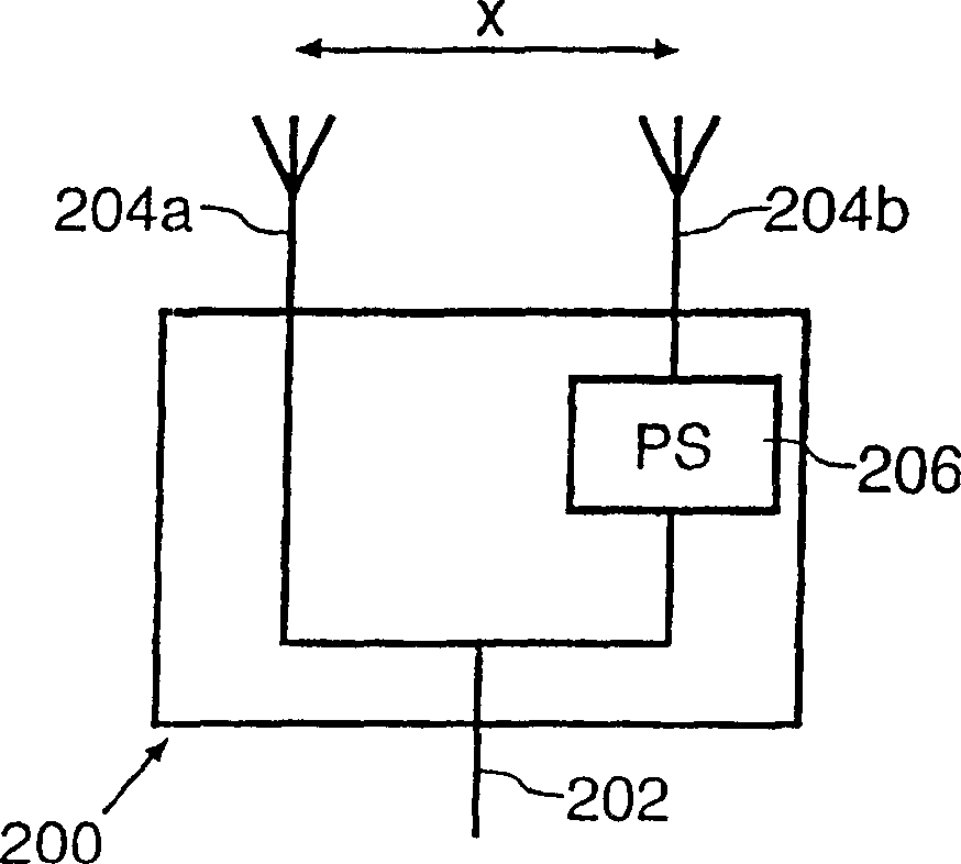
[0027] figure 2 An antenna diversity arrangement 200 is illustrated which will be used to describe an embodiment of the invention (the arrangement will act similarly for transmission and reception on the principle of reciprocity). Apparatus 200 includes an antenna feed 202, which carries a signal to be transmitted at an appropriate frequency and power level, and is divided and applied to first and second 204a, 204b. The signal applied to the second antenna 204b passes through a phase shifter 206, which phase shifts the signal by up to ±180° and adjusts the amplitude of the signal if desired.

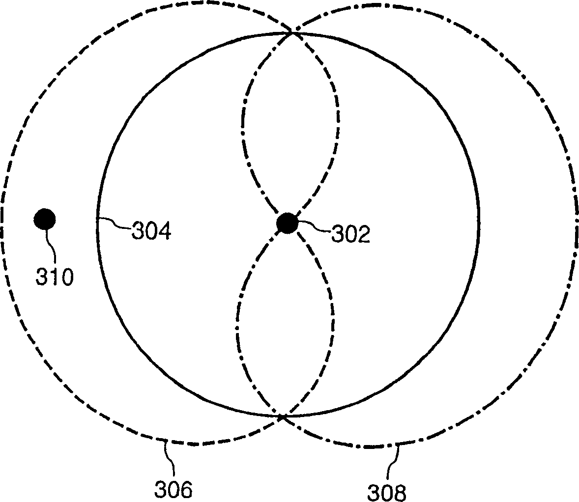
[0028] The ideal radiation pattern for this two-element array is a pair of identical but oppositely directed and orthogonal beams (i.e. beams with zero or very small envelope autocorrelation coefficient ρ e ), these beams together will provide omnidirectional coverage, while individually they receive the same power (on average all azimuths of arrival are equal) in a typical fading envi...


PUM


Abstract

An antenna diversity arrangement (200) comprises a plurality of antennas (204a, 204b) capable of forming a plurality of antenna beams. The amplitude and phase relationships between the signals driving each of the antennas (204a, 204b) are first determined for an arrangement where each antenna is replaced by a point source. The results of this analysis are then transformed by reference to the characteristics of the real antenna arrangement (200) to determine appropriate driving signals.The resultant antenna diversity arrangements (200) can have antennas (204a, 204b) located arbitrarily close to one another with near-zero correlation between any pair of the antenna beams, thereby providing a compact and effective arrangement.

Description

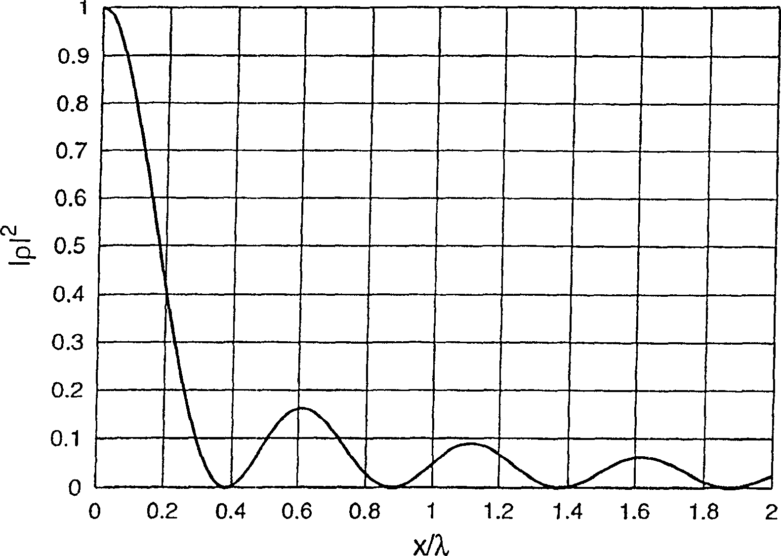
technical field [0001] The present invention relates to an antenna diversity arrangement comprising a plurality of antennas for providing angular diversity, to a wireless device including such an antenna diversity arrangement and to a method of operating such an arrangement. Background technique [0002] Antenna diversity is a known technique for adjusting multipath propagation benefits in radio communication systems. Narrowband diversity gains of about 10 dB have been proposed to be achievable when the signals received by the two (or more) antennas are sufficiently decorrelated. [0003] In A Statistical Theory of Mobile-Radio Reception, R.J Clarke, Bellsystems Technical Journal, Volume 47 No.6, pages 957 to 1000, the spatial correlation in the field of mobile radio environments is studied. In this paper, for a received vertically polarized wave the spatial envelope auto-correlation coefficient ρ e The known formula for is represented by [0004] ρ e =|ρ| 2 =...

Claims


Application Information

Patent Timeline
IPC IPC(8): H01Q21/29H04B7/04H01Q3/26H01Q1/24H01Q25/00H04B7/06H04B7/08
CPCH01Q1/241H01Q25/00H04B7/0617H01Q3/24
Inventor K·R·博伊尔
Owner NXP BV
Learn More