Electrolytic bath air gathering method

An electrolytic cell and gas collection technology, which is applied in the gas collection field of electrolytic cell flue gas, can solve the problems of large pressure loss, poor gas collection effect at the tail, and low gas collection efficiency, and achieve the effect of improving gas collection efficiency

Inactive Publication Date: 2005-05-18
SHENYANG ALUMINIUM MAGNESIUM INSTITUTE
View PDF0 Cites 1 Cited by
  • Summary
  • Abstract
  • Description
  • Claims
  • Application Information

AI Technical Summary

Problems solved by technology

This kind of single-pipe gas collection is more suitable for small-capacity electrolyzers. For large-capacity electrolyzers, due to the long gas-collecting pipeline, large pressure loss, and poor gas-collecting effect at the tail, the gas-collecting efficiency is not high, and the entire electrolyzer is damaged. The reduction of gas collection efficiency and the overflow of flue gas affect environmental protection
This has been shown in the existing high-capacity electrolyzer

Method used


Image

  • Electrolytic bath air gathering method
  • Electrolytic bath air gathering method
  • Electrolytic bath air gathering method

Examples


Embodiment Construction

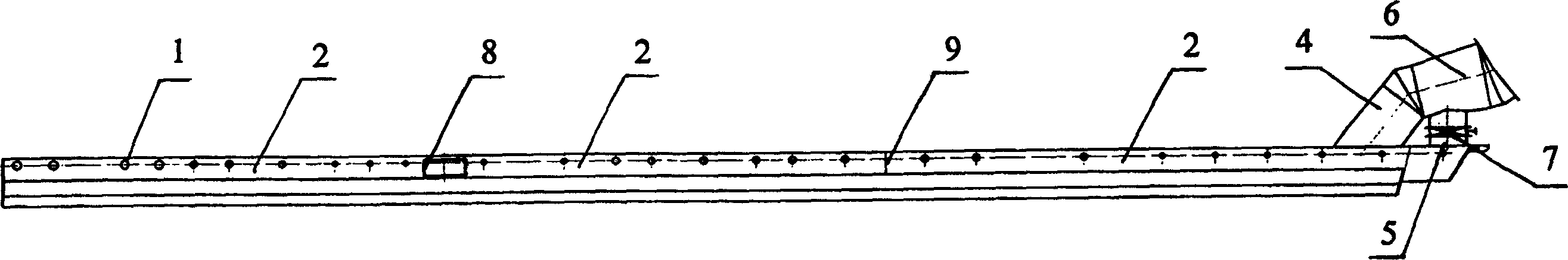
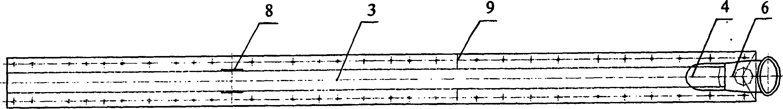
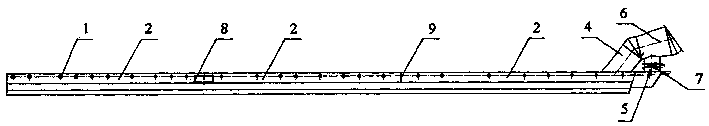
[0009] According to the smoke exhaust volume of a single tank and the smoke exhaust volume of each section of gas collection branch pipeline shall not exceed 4000m under standard conditions 3 / h, to determine the segment number of segmented gas collection; according to the principle of negative pressure and resistance balance, as well as the exhaust volume and flue gas flow rate of the branch pipe, determine the size of each gas collection branch pipeline. Taking a certain 300kA electrolytic cell as an example, it can be divided into three stages of gas collection. The gas collection branch pipe 2 is distributed along the longitudinal centerline of the electrolytic cell. Each section of the gas collection branch pipe 2 is welded by steel plates or steel pipes. are independent of each other; the first two sections of flue gas enter the gas collecting branch pipe 2 through the air inlet 1 or the gas collecting hood on the gas collecting branch pipe 2, and a communication hole 8 i...


PUM


Abstract

The invention discloses a gas collection method for an electrolytic cell, which solves the problem of low gas collection efficiency caused by the large negative pressure loss in the pipe along the direction of the gas collection pipe in the previous gas collection method. The invention adopts a segmented gas collection method, each section of flue gas enters the gas collection branch pipe (2) through the air inlet (1) or the gas collection cover, and each section of the gas collection branch pipe (2) is independent of each other, and is collected at the end of the electrolytic cell Afterwards, it is connected to the total air collecting pipe (6) of the electrolyzer. It ensures that the negative pressure of gas collection in each section is similar, and improves the gas collection efficiency of the flue gas in the electrolyzer.

Description

Technical field [0001] The invention relates to a method for collecting flue gas from an electrolyzer. Background technique [0002] With the continuous improvement of electrolytic aluminum technology, the capacity of electrolytic cells is getting larger and larger, and the flue gas (mainly CO 2 , CO, HF, CF 4 ) is also increasing. In a modern prebaked anode electrolyzer, the cathode, the upper mechanism and the side and end sealing covers form a closed space. Along the longitudinal center line of the electrolytic cell, install a longitudinally long gas-collecting pipe on the furnace of the electrolytic cell. There are many holes on the longitudinal sides and ends of the gas-collecting pipe, and its ends are connected with the purification system in the electrolytic workshop. ; Due to the action of the purification system fan, a negative pressure is formed in the gas-collecting pipeline. The flue gas in the tank is heated and diffuses upwards, enters the pipe through the...

Claims


Application Information

Patent Timeline
Patent Type & Authority Patents(China)
IPC IPC(8): C25C3/22
Inventor 杨晓东王桂芝邹智勇王汝良张荫蓬
Owner SHENYANG ALUMINIUM MAGNESIUM INSTITUTE
Why Eureka
Try Eureka