
Automatic temperature control device

A temperature control device and transmission ring technology, applied in biochemical cleaning devices, enzymology/microbiology devices, biochemical instruments, etc., can solve the problems of no gas production, no heat preservation of biogas digesters, inconvenient use, etc., and achieve the decomposition speed of organic matter Fast, microbial growth is active, and the effect of improving the sealing effect

Active Publication Date: 2021-03-02
SICHUAN UNIV
View PDF10 Cites 0 Cited by
  • Summary
  • Abstract
  • Description
  • Claims
  • Application Information

AI Technical Summary

Problems solved by technology

However, since rural household biogas digesters mostly use normal temperature fermentation, which is greatly affected by factors such as time, season, climate, and temperature difference between day and night, the gas production is very unstable, especially in winter, basically no gas production
In addition, the winter in northern my country is long and the temperature is generally lower than 0°C, so the promotion of biogas technology in northern my country has suffered serious setbacks; traditional biogas production devices can use solar energy for heating, and to a certain extent the use of solar thermal energy has improved The temperature of the biogas digester, but because the traditional biogas digesters have no heat preservation, or no constant temperature control equipment, or no heat storage equipment, etc., there is no device or method that can use solar heat to achieve constant temperature control of the biogas digester, and it is difficult Realize the continuous and stable production of biogas throughout the year, which brings inconvenience to use

Method used


Image

  • Automatic temperature control device
  • Automatic temperature control device
  • Automatic temperature control device

Examples


Embodiment Construction

[0028] The following will clearly and completely describe the technical solutions in the embodiments of the present invention with reference to the accompanying drawings in the embodiments of the present invention. Obviously, the described embodiments are only some, not all, embodiments of the present invention. Based on the embodiments of the present invention, all other embodiments obtained by persons of ordinary skill in the art without making creative efforts belong to the protection scope of the present invention.

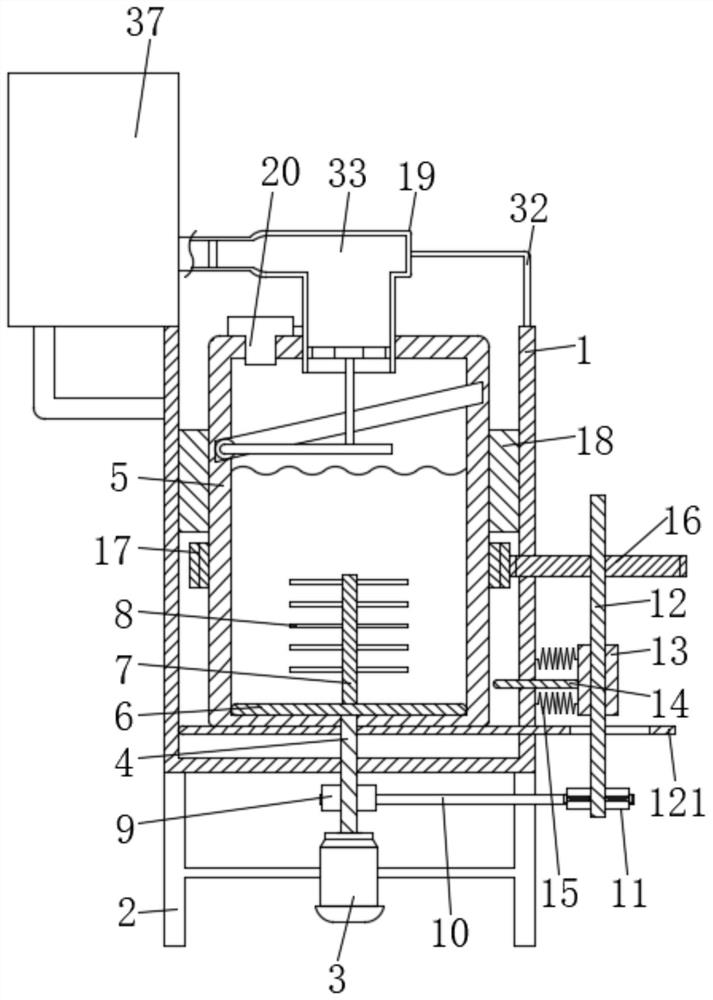
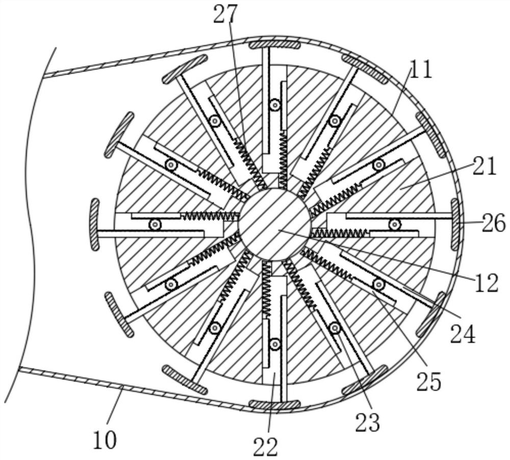
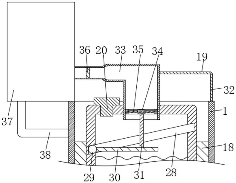
[0029] see Figure 1 to Figure 5 , the present invention provides a technical solution: an automatic temperature control device, including a fixed frame 1, the bottom of the fixed frame 1 is fixedly connected with a bracket 2, and the cooperation between the fixed frame 1 and the bracket 2 provides support and protection for the whole device. The bracket 2 is provided with a motor 3, and the top of the output shaft on the motor 3 is fixedly connected with a sh...


PUM


Abstract

The invention discloses an automatic temperature control device which comprises a fixing frame, a support is fixedly connected to the bottom of the fixing frame, a motor is arranged on the support, afirst shaft is fixedly connected to the top of the output shaft on the motor, and the surface of the first shaft penetrates through the lower surface of the fixing frame and is rotationally connectedwith the fixing frame. A fermentation bin is rotationally connected in the fixing frame in a limited mode, the first shaft penetrates through the lower surface of the fermentation bin and is fixedly connected with a sealing rotary disc, the lower surface of the sealing rotary disc is rotationally connected with the bottom of the inner wall of the fermentation bin in a limited mode, and a second shaft is fixedly connected to the circle center of the upper surface of the sealing rotary disc. Through cooperative use of the structures, the defects that in the actual use process, due to the fact that a traditional biogas digester does not have heat preservation or constant-temperature control equipment or heat storage equipment and the like, annual continuous and stable production of biogas isdifficult to achieve, the production efficiency is reduced, and inconvenience is brought to use are overcome.

Description

technical field [0001] The invention relates to the technical field of automatic temperature control equipment, in particular to an automatic temperature control device. Background technique [0002] Biogas is a high-quality, high-efficiency, green and environmentally friendly fuel, and has a very broad prospect of replacing traditional energy sources. In addition to being directly burned for cooking, drying agricultural and sideline products, heating, lighting, and gas welding, biogas can also be used as fuel for internal combustion engines and for the production of chemical raw materials such as methanol, formalin, and carbon tetrachloride. The feed liquid and sediment discharged from the biogas plant after fermentation contain rich nutrients and can be used as fertilizer and feed. [0003] The popularization and utilization of rural household biogas digesters in our country has been going on for a long time. Among them, the rural household water pressure biogas digester...

Claims


Application Information

Patent Timeline
IPC IPC(8): C12M1/38C12M1/34C12M1/107C12M1/02C12M1/00
CPCC12M21/04C12M23/38C12M23/46C12M23/48C12M27/02C12M37/04C12M41/12
Inventor 董骁汉王鹏何好
Owner SICHUAN UNIV
Learn More