Low-pressure gas well two-fluid supersonic atomization drainage gas recovery system and process thereof

A drainage gas production, supersonic technology, which is applied in the fields of fluid production, earthwork drilling, wellbore/well components, etc., can solve the problems of low gas flow rate, inability to perform atomization, restricting gas well production, etc., to improve gas production rate , Prevent clogging, good atomization effect

Inactive Publication Date: 2016-03-30
CHINA NAT PETROLEUM CORP CHUANQING DRILLING ENG CO LTD CHANGQING DOWNHOLE TECH CO
View PDF4 Cites 11 Cited by
  • Summary
  • Abstract
  • Description
  • Claims
  • Application Information

AI Technical Summary

Problems solved by technology

Since the gas field was exploited, the problem of eliminating fluid accumulation in the well has been plaguing the relevant gas production departments. So far, the following methods of drainage and gas production have been carried out, but none of them can be effectively solved
[0003] 1. Methanol injection for drainage and gas recovery has high operating cost and poor effect, and cannot meet the requirements of removing effusion
[0004] 2. Foam drainage for gas recovery has poor effect, high operating costs, and cannot fully remove fluid accumulation in the well
[0005] 3. The plunger drainage and gas recovery also seriously restrict the production of the gas well due to the long time of opening and closing the well, so it is not suitable
[0006] 4. The atomization and drainage in the well adopts swirling atomization and supersonic atomization respectively, both of which cannot be popularized and applied in gas fields because of their technical performance.
[0009] 1. When the atomizer is at the top of the liquid surface, because the gas extraction pressure of the oil pipe at the wellhead is as high as 3MPa, the production of the gas well is 5000 cubic meters per day, and the gas flow rate in the oil pipe is too small, 0.6 m / s, which is equivalent to the wind speed of the second to third grade , the gas in the well cannot bring the liquid into the Laval atomizer, and the atomization cannot be carried out, and the effusion still stays in the well
[0010] 2. When the atomizer is lowered below the liquid level, the gas-liquid ratio entering the atomizer is too small to achieve atomization. Even if a small amount of atomized liquid does not follow up in time due to lack of gas, the atomized liquid will fall back to the fog The upper part of the atomizer, can no longer atomize
[0011] Therefore, the current supersonic atomization does not have the atomization function and atomization conditions, and it needs to be researched and tested again

Method used


Image

  • Low-pressure gas well two-fluid supersonic atomization drainage gas recovery system and process thereof
  • Low-pressure gas well two-fluid supersonic atomization drainage gas recovery system and process thereof

Examples


Embodiment 1

[0042] The invention analyzes the reason why the supersonic atomizer cannot realize atomization in the well, and optimizes it to make it a special technology for atomization and liquid drainage. First, through the theory of fluid mechanics, the sufficient and necessary conditions for atomization in the gas well are obtained. The atomizer in the well can only atomize normally and eliminate the liquid accumulation in the well only if the atomizer in the well meets two conditions, that is, the inlet pressure of the atomizer must be greater than the outlet pressure. More than twice; atomized particle size 30-50um.

[0043] Due to the compressibility of gas, under a certain gas pressure difference on the ground, the technical parameters that can be atomized are not applicable when it is placed in a high-pressure environment in the well, and it follows the principle of isentropy. The Laval tube can reach supersonic speed. To achieve supersonic speed, the ratio of the inlet and outle...

Embodiment 2

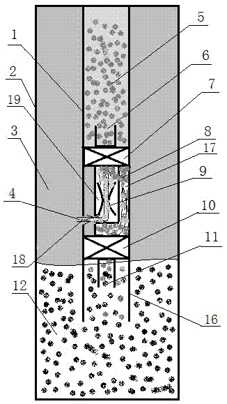
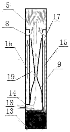
[0060] On the basis of Embodiment 1, the Laval tube 9 is arranged in a chamber 19, the upper end of the chamber 19 communicates with the atomization outlet 6, and the chamber 19 is located at the supersonic part of the Laval tube 9 The side wall of the chamber 19 is provided with an effusion inlet 8, and the liquid inlet channel 17 communicates with the effusion inlet 8; the chamber 19 is provided with a through hole on the side wall at the entrance of the lower end of the Laval tube 9, so that The air intake channel 18 communicates with the through hole. The oil pipe 1 is provided with a throttling pipe for controlling the flow rate of the liquid entering the atomizer. The throttle tube coil is installed in the oil pipe 1, and the aperture of the throttle tube is not less than 3mm. The aperture of the throttling tube is 3mm, and its length is 230m-250m. The inlet of the throttling tube is connected with a constant pressure valve, and the constant pressure valve is electrica...


PUM


Abstract

The invention belongs to the technical field of drainage gas recovery process, and specifically provides a low-pressure gas well two-fluid supersonic atomization drainage gas recovery system and a process thereof, wherein a wellbore is taken as a good gas-liquid separator, and gas in a casing pipe is introduced to a Laval nozzle to form supersonic gas flow; by utilizing the characteristic that the air pressure of the casing pipe is higher than that of an oil pipe, accumulated liquid in a well is introduced to a supersonic area of the Laval nozzle through the oil pipe, so as to form a two-fluid supersonic atomization technology. Moreover, through a control method of digitized gas recovery, the ratio of pressure at an inlet to pressure at an outlet, entering an atomizer reaches an atomization condition, through a constant pressure valve switching technology and a diameter extra-long pipe restriction decompression technology, the maximum flow of accumulated liquid entering the atomizer is controlled, the vapor liquid ratio of atomization liquid drainage is reached, and the critical technical problem that the atomizer is liable to block is solved. The system and the process thereof, provided by the invention can effectively utilize energy in the well to perform atomization liquid drainage, solve the problem of accumulated liquid in the well, improve the gas recovery speed and reduce gas recovery cost.

Description

technical field [0001] The invention belongs to the technical field of drainage gas recovery technology, and specifically provides a low-pressure gas well dual-fluid supersonic atomization drainage gas recovery system and its technology. Background technique [0002] Changqing gas field is a typical "three low" gas reservoir. With the increase of domestic demand for natural gas, the development scale is getting bigger and bigger, the formation pressure is getting lower and lower, and the fluid accumulation in the well is getting more and more serious. Even at the stage of intermittent gas production, drainage gas production has become a constraint on the production capacity of gas wells. The biggest constraint factor of production speed, PetroChina has to spend a lot of money and scientific research to develop drainage and gas recovery technology. Since the gas field was exploited, the problem of removing fluid accumulation in the well has been perplexing the relevant gas p...

Claims


Application Information

Patent Timeline
Patent Type & Authority Applications(China)
IPC IPC(8): E21B43/12
CPCE21B43/121E21B43/122
Inventor 邓继学孙虎王祖文白明伟景志明刘培润刘国良欧阳伟平韩静静费节高李富强米虎宁韩蓉田军
Owner CHINA NAT PETROLEUM CORP CHUANQING DRILLING ENG CO LTD CHANGQING DOWNHOLE TECH CO
Why Eureka
Try Eureka