Eureka AIR delivers breakthrough ideas for toughest innovation challenges, trusted by R&D personnel around the world.

Fuel battery unit with electric field-membrane electrode combined structure and a reversible regenerable oxyhydrogen electrolysis unit thereof

A fuel cell and combined structure technology, which is applied in the field of fuel cell devices and reversible regenerative hydrogen-oxygen electrolysis devices, can solve the problems of poor power density stability, decreased power generation efficiency, and shortened working life, so as to improve electrolysis efficiency and reduce The effect of decomposing voltage and improving performance

Active Publication Date: 2009-09-23
郭建国 +1
View PDF1 Cites 9 Cited by
  • Summary
  • Abstract
  • Description
  • Claims
  • Application Information

AI Technical Summary

Problems solved by technology

However, due to the reduction in the amount of platinum used as a catalyst material for the cathode and anode, the power density of methanol fuel cells (DMFC) and proton exchange membrane fuel cells (PEMFC) is not stable during long-term operation, resulting in a gradual decline in power generation efficiency and shortened working life.

Method used

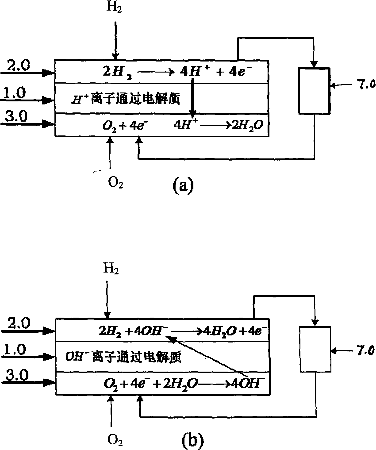
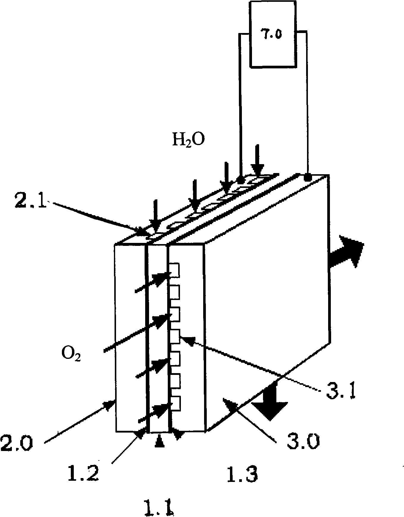

Image

  • Fuel battery unit with electric field-membrane electrode combined structure and a reversible regenerable oxyhydrogen electrolysis unit thereof
  • Fuel battery unit with electric field-membrane electrode combined structure and a reversible regenerable oxyhydrogen electrolysis unit thereof
  • Fuel battery unit with electric field-membrane electrode combined structure and a reversible regenerable oxyhydrogen electrolysis unit thereof

Examples


Embodiment 1

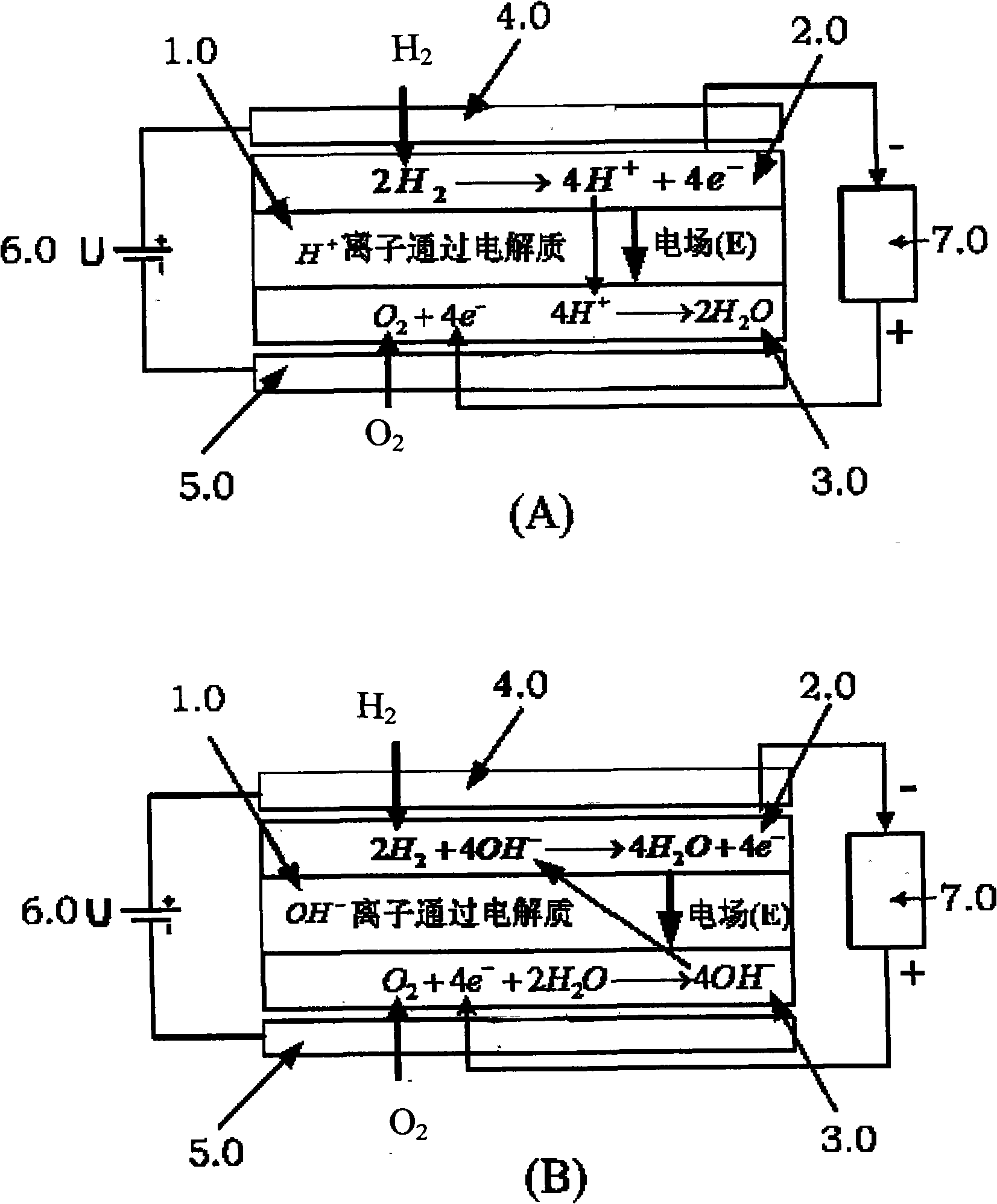
[0038] refer to image 3 As shown, a fuel cell device with an electric field-membrane electrode (E-field MEA) combined structure is composed of electrolyte 1.0, anode 2.0, cathode 3.0, electric field positive electrode 4.0, and electric field negative electrode 5.0. Among them, the DC power supply 6.0 is the power supply for the positive pole of the electric field 4.0 and the negative pole of the electric field 5.0. Its main function is to provide a stable or regulated internal electric field E for the three-in-one component composed of the membrane electrode MEA. Load 7.0 is an external load powered by a fuel cell. Among them, (A) and (B) respectively represent acidic and alkaline electrolyte fuel cells.

[0039] refer to image 3 As shown, the operating principle of a fuel cell device with an electric field-membrane electrode (E-field MEA) combined structure in this embodiment is:

[0040] Anode-cathode reactions and electron flow in acidic electrolyte (PEM) fuel cells: A...

Embodiment 2

[0046] This embodiment 2 "a water electrolysis cell device with an electric field-membrane electrode (E-field MEA) combined structure" is composed of electrolyte 1.0, anode 2.0, cathode 3.0, electric field positive electrode 4.0, and electric field negative electrode 5.0. Among them, the DC power supply 6.0 is the power supply for the positive pole of the electric field 4.0 and the negative pole of the electric field 5.0. Its main function is to provide a stable or regulated internal electric field E for the three-in-one component composed of the membrane electrode MEA. The power supply 7.0 is the electrolysis power supply of the water electrolysis cell.

[0047] The working principle of this embodiment 2 "a water electrolysis cell device with an electric field-membrane electrode (E-field MEA) combined structure" is: at the positive electrode, water is oxidized to release electrons 2H 2 O→O 2 +4H + +4e - The reaction produces oxygen. In the negative electrode H + Removed ...


PUM


Abstract

The invention relates to a fuel battery unit with an electric field-membrane electrode combined structure and a reversible regenerable oxyhydrogen electrolysis unit thereof. The fuel battery unit has the structure that electrolyte is arranged between an anode and a cathode. The fuel battery unit is characterized in that an electric field anode insulated with the anode is arranged outside the anode; an electric field cathode insulated with the cathode is arranged outside the cathode; and the electric field anode and the electric field cathode are connected with a DC power supply. The fuel battery unit with the electric field-membrane electrode combined structure can effectively reduce the activation loss, the penetration of the fuel, the internal short-circuit current and the ohm loss, improves the performance of the fuel battery unit and overcomes the defect that prior fuel battery units cannot reduce the activation loss. The application of the fuel battery unit with the electric field-membrane electrode combined structure in the reversible regenerable oxyhydrogen electrolysis unit can also reduce the activation loss and improve the electrolysis efficiency.

Description

technical field [0001] The invention relates to the application field of fuel cells, in particular to a fuel cell device with an electric field-membrane electrode assembly (E-fieldMEA) structure and a reversible regenerative hydrogen-oxygen electrolysis device. Background technique [0002] A fuel cell is a device that directly converts the chemical energy of hydrogen and oxygen into electrical energy through an electrode reaction. The biggest feature of this device is that since no combustion is involved in the reaction process, its energy conversion efficiency is not limited by the "Carnot cycle", and its energy conversion rate is as high as 60% to 80%. 2 to 3 times. In addition, it also has the advantages of diversified fuels, clean exhaust, low noise, and small environmental pollution. [0003] The current fuel cell structure is a three-in-one assembly MEA (Membrane Electrode Assembly) composed of "anode-electrolyte-cathode". The type of electrolyte determines the ope...

Claims


Application Information

Patent Timeline
IPC IPC(8): H01M8/08H01M8/10H01M8/04H01M8/24H02J7/00C25B1/04C25B9/10C25B9/23
CPCH01M8/1011H01M8/186H01M2008/1095H01M8/04261Y02E60/523Y02E60/528H01M8/083Y02E60/366H01M8/04197Y02E60/50Y02E60/36
Inventor 郭建国毛星原
Owner 郭建国
Why Eureka
Eureka Blog
Learn More