Method for diagnosing catalyzing device of IC engine and IC engine

A technology for catalytic converters and internal combustion engines, applied in the field of catalytic converters, can solve problems such as catalytic converter aging, and achieve the effect of fast execution possibility and simple execution possibility

Inactive Publication Date: 2005-05-25
ROBERT BOSCH GMBH
View PDF0 Cites 4 Cited by
  • Summary
  • Abstract
  • Description
  • Claims
  • Application Information

AI Technical Summary

Problems solved by technology

This loading and unloading and the associated conversion of nitrogen oxides to nitrogen and oxygen will lead to the aging of the catalyst

Method used


Image

  • Method for diagnosing catalyzing device of IC engine and IC engine
  • Method for diagnosing catalyzing device of IC engine and IC engine
  • Method for diagnosing catalyzing device of IC engine and IC engine

Examples


Embodiment Construction

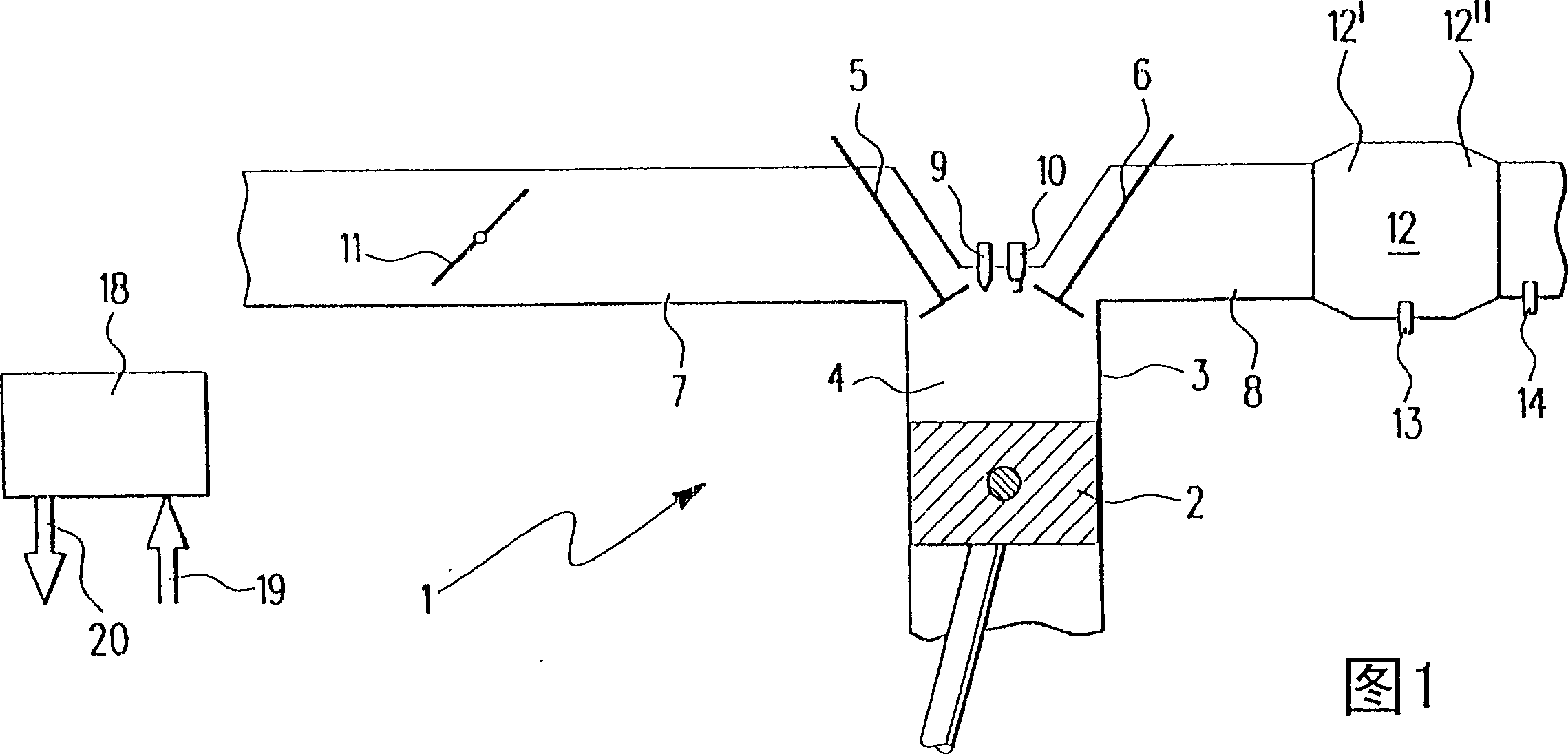
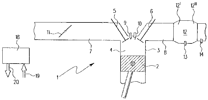
[0018] FIG. 1 shows an internal combustion engine 1 of a motor vehicle, in which a piston 2 reciprocates in a cylinder 3 . Cylinder 3 is provided with a combustion chamber 4 which is delimited essentially by piston 2 , intake valve 5 and exhaust valve 6 . An intake pipe 7 is connected to the intake valve 5 and an exhaust pipe 8 is connected to the exhaust valve 6 .

[0019] In the area of ​​intake valve 5 and exhaust valve 6 , an injection valve 9 and a spark plug 10 protrude into combustion chamber 4 . Fuel can be injected into combustion chamber 4 via injector 9 . The fuel in combustion chamber 4 can be ignited by means of spark plug 10 .

[0020] In the intake manifold 7 there is a rotatable throttle valve 11 through which air is fed into the intake manifold 7 . The air quantity fed depends on the angular position of the throttle valve 11 . In the exhaust line 8 there is a catalytic converter 12 which serves to purify the exhaust gases produced by the combustion of fuel...


PUM


Abstract

The invention describes an internal combustion engine, in particular a motor vehicle internal combustion engine (1), in which fuel can be injected directly into a combustion chamber (4) during an intake phase in a first operating mode and during a compression phase in a second operating mode and burn. The exhaust gases formed during the combustion can be fed into a catalytic converter ( 12 ). In the second operating mode, additional fuel can be injected after the primary combustion via a control device (18). The temperature of the exhaust gas can likewise be measured by the control device ( 18 ) in or downstream of the catalytic converter ( 12 ) and compared with a threshold value.

Description

technical field [0001] The invention relates to a method for diagnosing a catalytic converter of an internal combustion engine, in particular a motor vehicle internal combustion engine, wherein fuel is directly injected into a combustion chamber and combusted during an intake phase in a first operating mode and during a compression phase in a second operating mode, and The exhaust gases formed during the combustion are fed to a catalytic converter. The invention also relates to an internal combustion engine, in particular a motor vehicle internal combustion engine. Background technique [0002] Such a method, such a control device and such an internal combustion engine are known, for example, from the so-called petrol direct injection technique. In this case, fuel is injected into the combustion chamber of the internal combustion engine during the intake phase in the homogeneous mode of operation or during the compression phase in the stratified mode of operation. Uniform ...

Claims


Application Information

Patent Timeline
Patent Type & Authority Patents(China)
IPC IPC(8): F01N11/00F02D41/40F02D43/00F01N3/20F01N3/36F01N9/00F02D41/04F02D41/30F02D45/00
CPCF01N9/005F01N11/002F01N2550/02F02D41/1446F02D41/3023F02D41/405F02D2041/389Y02T10/40F02D41/40
Inventor 埃贝哈德·施奈贝尔安德烈亚斯·克林霍尔格·贝尔曼
Owner ROBERT BOSCH GMBH
Why Eureka
Try Eureka