
Valve, especially radiator valve

A valve shell and valve seat technology, which is applied in the field of radiator valves, can solve problems such as poor quality of installation workers for installing radiator valves.

Inactive Publication Date: 2005-05-25
DANFOSS AS
View PDF1 Cites 0 Cited by
  • Summary
  • Abstract
  • Description
  • Claims
  • Application Information

AI Technical Summary

Problems solved by technology

[0005] The danger of incorrectly installing radiator valves arises not only from poorly qualified installers, but also when, in older houses or older installations, one can no longer determine exactly which line is used for water intake and which line is used for drainage , also creates the danger that

Method used


Image

  • Valve, especially radiator valve
  • Valve, especially radiator valve
  • Valve, especially radiator valve

Examples


Embodiment Construction

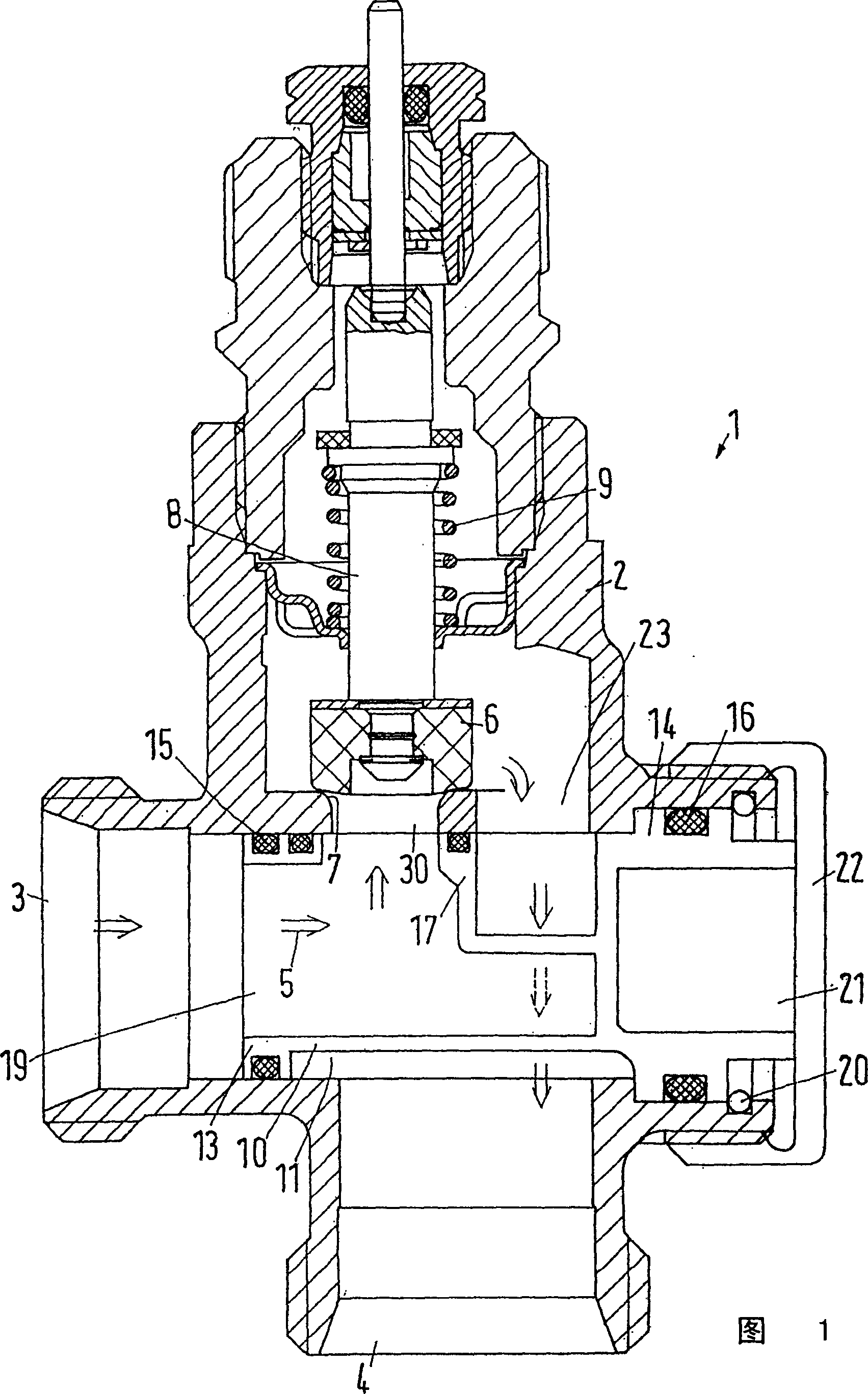
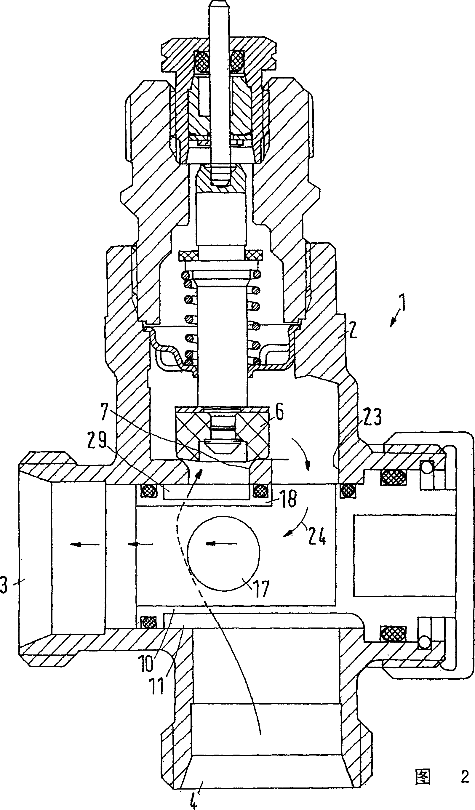
[0022] FIG. 1 shows a radiator valve 1 with a valve housing 2 having a water inlet connection 3 and an outlet connection 4 . Arrow 5 indicates the flow path of heating fluid such as hot water passing through the radiator valve. A shut-off mechanism is arranged in the flow path, which has a valve slide 6 which cooperates with a valve seat 7 . The spool 6 can be pushed by the valve stem 8 towards the valve seat 7 or away from the valve seat in the manner indicated schematically. A spring 9 is provided, which pushes the spool 6 away from the valve seat 7 without external force.

[0023] The direction of flow shown in FIG. 1 is "normal" flow, in which water flows through the valve seat 7 to the valve core 6 . As a result, there is no problem opening or closing. If the spool 6 moves towards the valve seat 7 , the water flow is throttled step by step in such a way that the gap between the spool 6 and the valve seat 7 is continuously reduced, and the drive of the spool 6 is only v...


PUM


Abstract

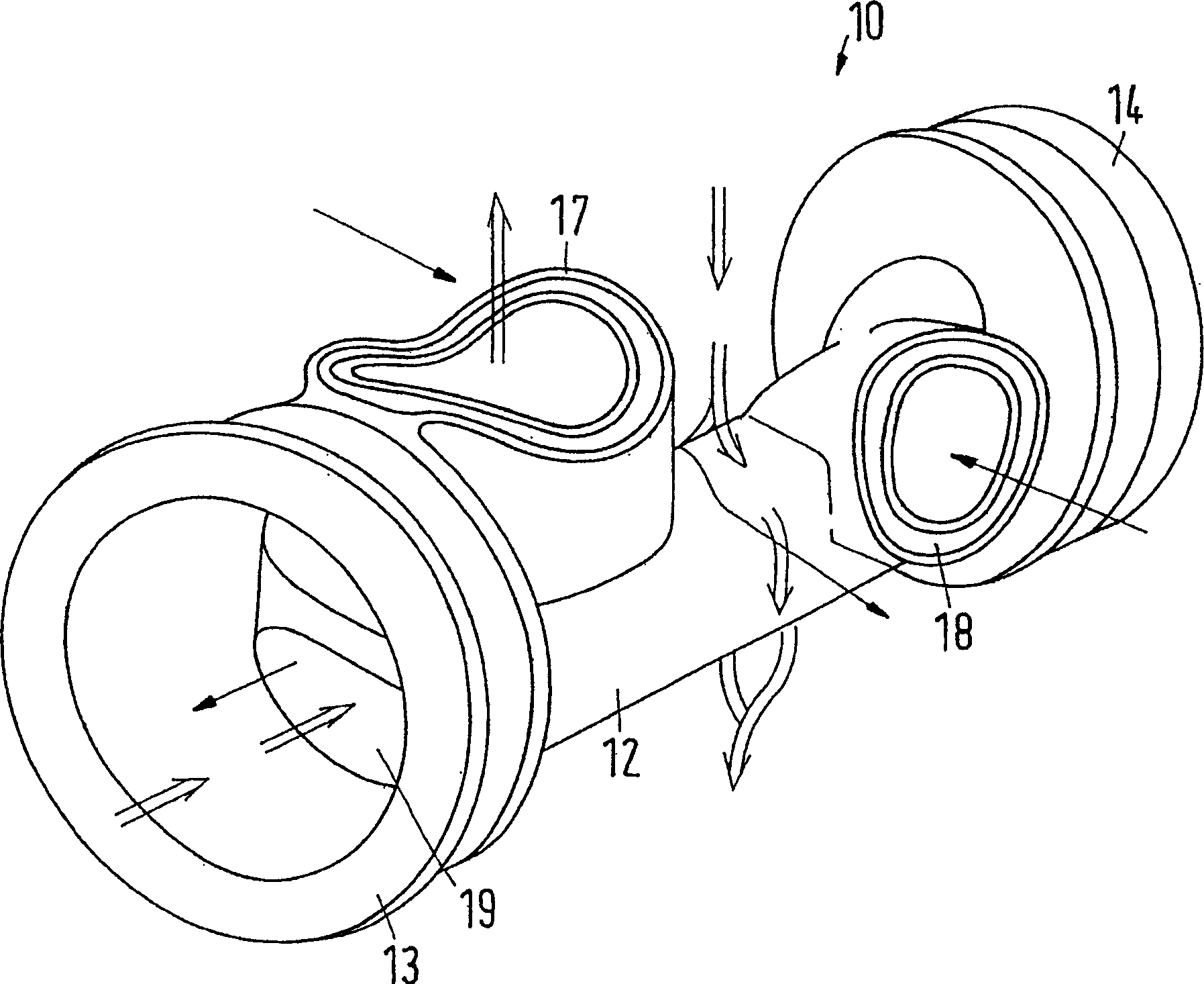
The radiator valve has a valve seat system with two outlets (17, 29), one of which connects with the valve inlet (3) and the other with the outlet (4). The valve body (6) can be adjusted to cooperate with either of the outlets on the seat.

Description

technical field [0001] The invention relates to a valve, and in particular a radiator valve, which has a valve housing with a water inlet connection and a water outlet connection, wherein in the flow path between the water inlet connection and the water outlet connection a valve with A closing mechanism of a spool and a seat mechanism. Background technique [0002] Such a valve designed as a radiator valve is known from WO 99 / 22282. [0003] Usually, in such radiator valves, the flow direction is predetermined and marked with an arrow on the outside of the valve housing. Attention should be paid to flow direction to avoid noticeable disturbances mainly through harsh noise. Usually, the side of the blocking mechanism close to the valve seat is connected to the water inlet pipe joint, and the side of the blocking mechanism close to the valve core is connected to the water outlet pipe joint. When the valve core is about to move to the valve seat, the phenomenon that the wate...

Claims


Application Information

Patent Timeline
IPC IPC(8): F16K1/36F16K47/02F16K1/42F16K1/52F16K11/085F24D19/10G05D23/02
CPCF16K11/085F16K1/52
Inventor J·D·梅斯默A·B·拉森
Owner DANFOSS AS
Learn More