Supercharge Your Innovation With Domain-Expert AI Agents!

Electric brush holder for rotary motor

A technology for rotating electrical machines and holding devices, applied in electromechanical devices, rotating current collectors, circuits, etc., can solve problems such as inability to respond quickly, increase in vibration area, and increase in brush prices.

Inactive Publication Date: 2005-05-25
MITSUBISHI ELECTRIC CORP
View PDF1 Cites 0 Cited by
  • Summary
  • Abstract
  • Description
  • Claims
  • Application Information

AI Technical Summary

Problems solved by technology

However, due to the installation of the anti-vibration plate on the brush, the brush itself has a non-standard structure, which not only increases the price of the brush, but also requires special parts when replacing parts.
In addition, installing the anti-vibration plate will increase the vibration area at the same time, which will limit the effect of preventing noise

Method used


Image

  • Electric brush holder for rotary motor
  • Electric brush holder for rotary motor
  • Electric brush holder for rotary motor

Examples


Embodiment Construction

[0028] Embodiment 1

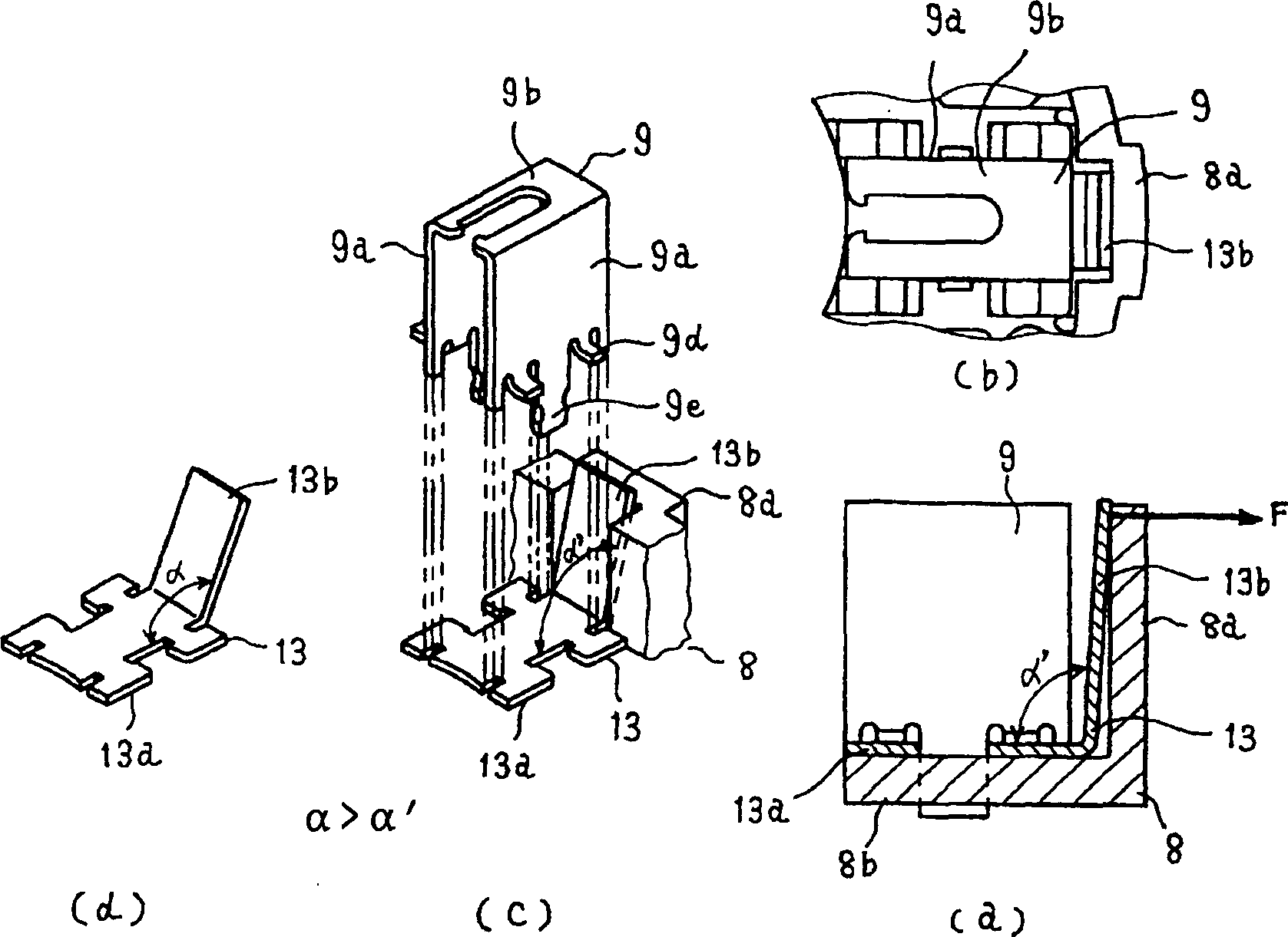
[0029] figure 1 is a structural diagram of a brush holding device according to Embodiment 1 of the present invention, figure 2 with image 3 As an explanatory diagram for explaining its effects, the same parts as those of the above-mentioned conventional example are assigned the same symbols. exist figure 1 Among them, 8 is a retainer mounting body composed of an arc-shaped outer wall portion 8a and a base plate portion 8b, and 9 is a front end portion with two side walls 9a and an upper wall 9b made into a "U" shape and a "U" shape. The brush holder with the protrusion 9c for the riveting part and the protrusion 9d for the fixed position, 13 is a spring holder, which is installed on the brush holder installation body 8 together with the brush holder 9, forming a "U" shape The wall part 13a of the bottom surface wall of the brush holder 9 and the holding part 13b which is located at the counter-commutator side opening of the brush holder 9 and supp...


PUM


Abstract

The present invention relates to a brush unit for a rotating electric machine, the holding unit has good brush vibration damping characteristics, thereby reliably reducing vibration and noise. The brush holding device includes: a brush holder (9) for accommodating and holding a brush (10) in sliding contact with the commutator; The brush holder mounting body (8) composed of the outer wall portion (8a) facing the outer diameter peripheral surface of the commutator (5) on the outer diameter side of the brush holder (9) is provided with a The brush holder is installed and fixed on the brush holder installation body (8), and one end of the spring (11) between the brush (10) and the brush (10) at the opening of the brush holder on the side of the commutator is held The spring retainer (13) of the holding part (13b) that lives. The holding portion (13b) of the spring holder is crimped and fixed to the outer wall portion (8a) of the brush holder mounting body (8).

Description

field of invention [0001] The present invention relates to a rotating electric machine, and more particularly, the present invention relates to a low-vibration, low-noise brush holder for an auxiliary electric machine suitable for an electric power control device. Background technique [0002] Figure 9 is a sectional view of the structure of a conventional rotating electrical machine using a commutator and brushes, Figure 10 It is a top view of the bracket with the brush holding device of the rotating electric machine seen from the inside of the rotating electric machine, and Fig. 11 is a structural diagram of a conventional brush holding device, Figure 12 This is an explanatory diagram related to the formation of brush vibration. exist Figure 9 Among them, 1 is the yoke of the rotating electrical machine, 2 is the magnet of the excitation device provided on the inner diameter surface of the yoke iron, and 3 is the rotor of the rotating electrical machine having the sha...

Claims


Application Information

Patent Timeline
Patent Type & Authority Patents(China)
IPC IPC(8): H01R39/38H01R39/40H01R39/415H02K13/00
Inventor 白石健司桥本征史久保田胜
Owner MITSUBISHI ELECTRIC CORP
Features
  • R&D
  • Intellectual Property
  • Life Sciences
  • Materials
  • Tech Scout
  • Unparalleled Data Quality
  • Higher Quality Content
  • 60% Fewer Hallucinations
Learn More