Thermoelectric device

Active Publication Date: 2005-01-27
KK TOSHIBA
View PDF8 Cites 46 Cited by
  • Summary
  • Abstract
  • Description
  • Claims
  • Application Information

AI Technical Summary

Benefits of technology

[0009] It is an object of the present invention to provide a thermoelectric device excellent in reliability, in which joint parts of thermoelectric elements and the thermoelectric eleme

Problems solved by technology

Because of such a difference in thermal deformation, in some cases, joint parts of the thermo

Method used


Image

  • Thermoelectric device
  • Thermoelectric device
  • Thermoelectric device

Examples


first embodiment

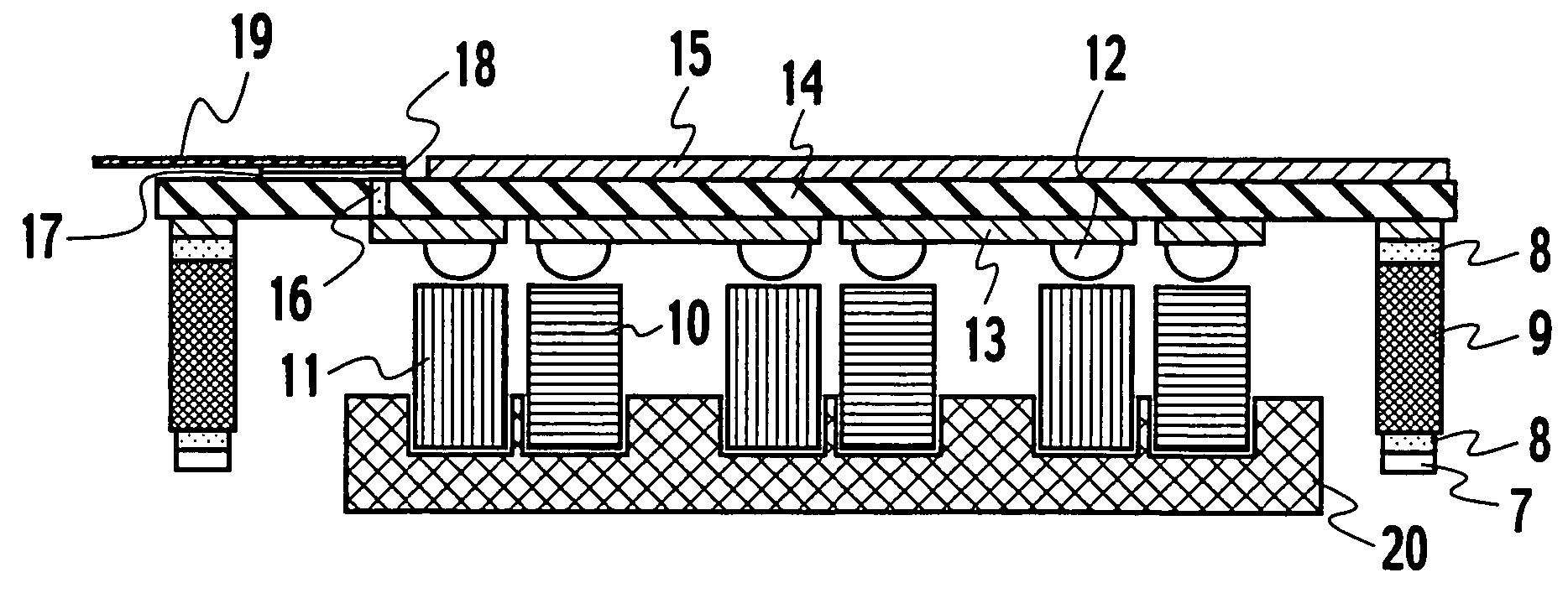
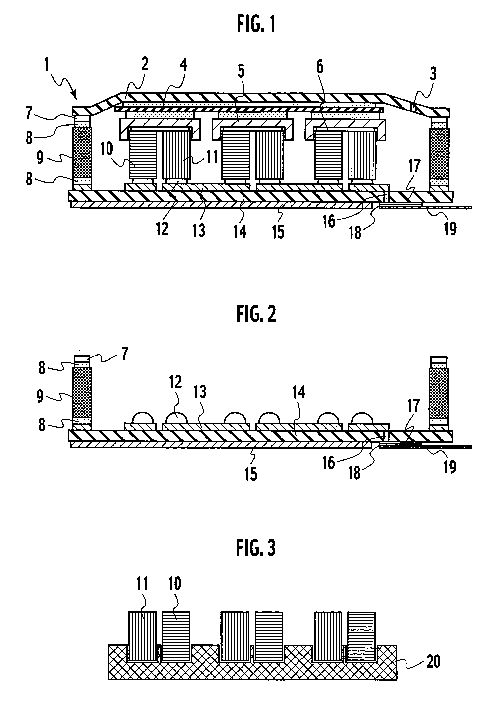
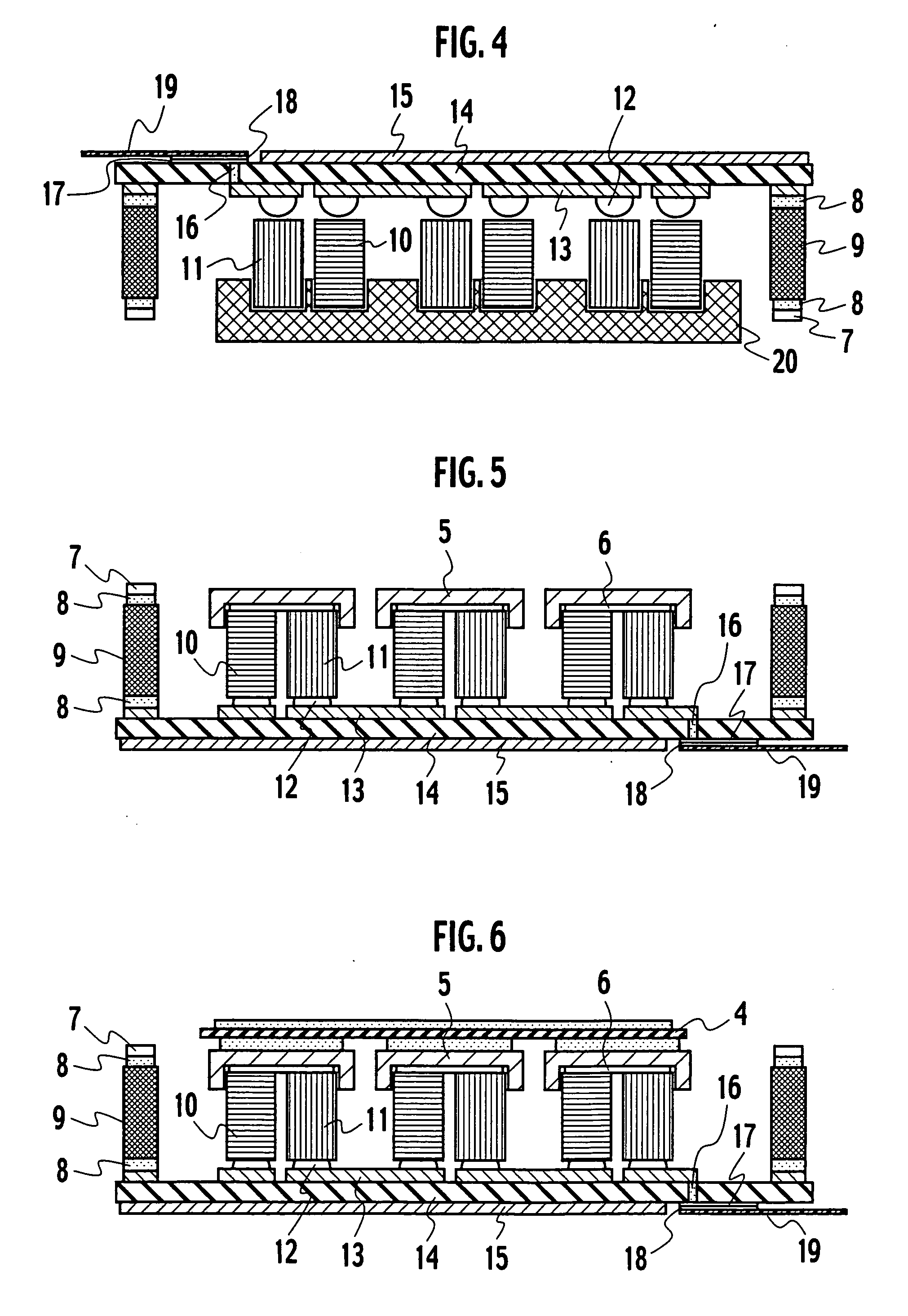
[0032]FIG. 1 shows a cross-sectional structure of a thermoelectric device of a The thermoelectric device 1 includes a plurality of p-type thermoelectric elements 10 and n-type thermoelectric elements 11, one end surfaces of which are arranged on a heat-radiating-side board 14 serving as a wiring board. A plurality of heat-radiating-side electrodes 13, arrayed in accordance with positions where the respective thermoelectric elements 10 and 11 are to be arranged, are arrayed in an array fashion on a planer surface of the heat-radiating-side board 14. With regard to the p-type thermoelectric elements 10 and the n-type thermoelectric elements 11, the heat-radiating-side end surfaces of these thermoelectric elements and the heat-radiating-side electrodes 13 are joined to each other by solders 12.

[0033] On heat-absorbing-side end surfaces as the other end surfaces of the respective thermoelectric elements 10 and 11, a heat-absorbing-side insulating board 4, heat-absorbing-side electrodes...

second embodiment

[0049]FIG. 7 shows a cross-sectional structure of a thermoelectric device of a This thermoelectric device 21 is characterized in that the lid 2 and the heat-absorbing-side electrodes 5 are brought into direct contact with each other without separately preparing the insulating board.

[0050] It is necessary for the lid 2 to be joined to the frame 9 by welding in a similar way to the first embodiment, and accordingly, the lid 2 is made of metal. In this case, it is necessary that each of the heat-absorbing-side electrodes 5 be electrically independent of the others, and accordingly, it is necessary to electrically insulate the lid 2 and the heat-absorbing-side electrodes 5 from each other. In this connection, insulating films such as oxide films are formed on contact surfaces of the lid 2 with the heat-absorbing-side electrodes 5. Besides this, it is possible to constitute the thermoelectric device by depositing the insulating films on contact surfaces of the heat-absorbing-side electr...

third embodiment

[0052]FIG. 8 shows a cross-sectional structure of a thermoelectric device of a This thermoelectric device 22 is characterized in that a frame connecting a lid 71 and the heat-radiating-side board 14 to each other is composed of a frame 23 and a frame 24, which are obtained by dividing the frame into two in the height direction. The lid 71 and the heat-radiating-side board 14 are composed of ceramics such as Al2O3, and the frame 23 and the frame 24 are composed of, for example, Kovar in order to be welded.

[0053] The lid 71 having a metal portion 72 to which the frame 23 is brazed with silver brazing 8 interposed therebetween and the heat-radiating-side board 14 having a metal portion 73 to which the frame 24 is brazed with the silver brazing 8 interposed therebetween are fitted to each other on abutting surfaces of the frame 23 and the frame 24. Then, a portion where the frame 23 and the frame 24 overlap with each other is welded by laser. Furthermore, the sealing hole 3 is closed b...


PUM

PropertyMeasurementUnit
Pressureaaaaaaaaaa
Electrical conductoraaaaaaaaaa
Thermoelectricityaaaaaaaaaa

Abstract

In order to provide a highly reliable thermoelectric device, in a thermoelectric device, a plurality of heat-radiating-side electrodes, arranged in accordance with positions where respective thermoelectric elements are to be arranged, are arrayed in an array fashion on a planer surface of a heat-radiating-side board. Heat-radiating-side end surfaces of the plurality of p-type thermoelectric elements and n-type thermoelectric elements and the heat-radiating-side electrodes are joined together by solders. Heat-absorbing-side electrodes are brought into sliding contact with heat-absorbing-side end surfaces of these thermoelectric elements.

Description

CROSS-REFERENCE TO RELATED APPLICATIONS [0001] This application is based upon and claims the benefit of priority from Japanese Patent Application No. 2003-202121 filed on Jul. 25, 2003 and Japanese Patent Application No. 2004-90250 filed on Mar. 25, 2004; the entire contents of which are incorporated herein by reference. BACKGROUND OF THE INVENTION [0002] 1. Field of the Invention [0003] The present invention relates to a thermoelectric device configured in a manner that heat-absorbing-side electrodes are attached onto heat-absorbing surfaces of a plurality of thermoelectric elements, heat-radiating-side electrodes are attached onto heat-radiating surfaces of the respective thermoelectric elements, and all of the thermoelectric elements are connected electrically in series and thermally in parallel. Particularly, the present invention relates to a thermoelectric device having good manufacturability and excellent joint reliability. [0004] 2. Description of the Related Art [0005] A th...

Claims


Application Information

Patent Timeline
IPC IPC(8): H01L35/06H01L35/08H01L35/30H01L35/32H01L35/34H02N11/00
CPCH01L35/06H01L35/30H01L35/32H01L35/34Y10T29/4913H05K2201/10219Y10T29/49144Y10T29/49002H05K1/0204H10N10/813H10N10/17H10N10/13H10N10/01
Inventor TATEYAMA, KAZUKISOGOU, TAKAHIROIGUCHI, TOMOHIROSAITO, YASUHITOARAKAWA, MASAYUKIKONDO, NARUHITOTSUNEOKA, OSAMUHARA, AKIHIRO
Owner KK TOSHIBA
Why Eureka
Try Eureka