Lightning protection of a pitch-controlled wind turbine blade

a technology of pitch control and wind turbine blades, which is applied in the direction of wind turbines, wind turbines, electric cable installations, etc., can solve the problem of weak electric resistan

Active Publication Date: 2008-06-24
LM GLASSFIBER
View PDF6 Cites 45 Cited by
  • Summary
  • Abstract
  • Description
  • Claims
  • Application Information

AI Technical Summary

Benefits of technology

[0010]The object of the invention is to provide an improved lightning down-conducting arrangement for a wind turbine which ensures to a maximum extent that the lightning strikes in the receptors of the blade or the outer lightning down-conductors so as subsequently to be guided safely to the ground through the lightning down-conducting arrangement without causing damage to the wind turbine. A further object is to protect the pitch bearings against electrical currents.
[0011]The object of the invention is obtained by providing a sliding contact connection parallel to the spark gap between the lightning down-conductor and the rotor hub, said sliding contact connection ensuring an electrical contact between said lightening down-conductor and said rotor hub irrespective of the pitch angle of the blade. In this way, a permanent electrical connection can be obtained between the lightning down-conductor of the blade and the rotor hub. Furthermore, upward leaders can be generated from the receptors of the blade or the outer lightning down-conductors with the result that the probability of lightning striking in the receptor or in the outer lightning conductors has been optimised. During the actual main discharge, the so-called return stroke, where a very strong current flows within a very short period of time, an electric arc is simultaneously generated in the spark gap due to the very strong electrical potential applying after the short circuiting of the leaders. As a result the electrical resistance is very weak in the spark gap with the result that the lightning current passes through the spark gap to the ground. As the electrical resistance in the spark gap is much weaker than the contact resistance in the sliding contact connection, only a small non-destructive portion of the lightning current passes through the sliding contact connection. The sliding contact connection ensures that a permanent electrical connection applies between the lightning down-conductor of the blade and the rotor hub irrespective of the pitch angle of the blade. The pitch bearing is completely protected against the passing of current and is thereby ensured a prolonged life because no sparkovers and migrations of material occur between the pitch bearing members.
[0014]According to a preferred embodiment, the spark gap is provided between the contact member and a spark gap member. This embodiment is particularly simple because the contact member is used for both the sliding contact connection and the spark gap connection.
[0015]According to a particularly advantageous embodiment, the collector shoe and the spark gap member are combined in one contact unit, thereby obtaining a particularly simple and compact structure which is easily maintained or replaced.

Problems solved by technology

As a result the electrical resistance is very weak in the spark gap with the result that the lightning current passes through the spark gap to the ground.

Method used


Image

  • Lightning protection of a pitch-controlled wind turbine blade
  • Lightning protection of a pitch-controlled wind turbine blade
  • Lightning protection of a pitch-controlled wind turbine blade

Examples


Embodiment Construction

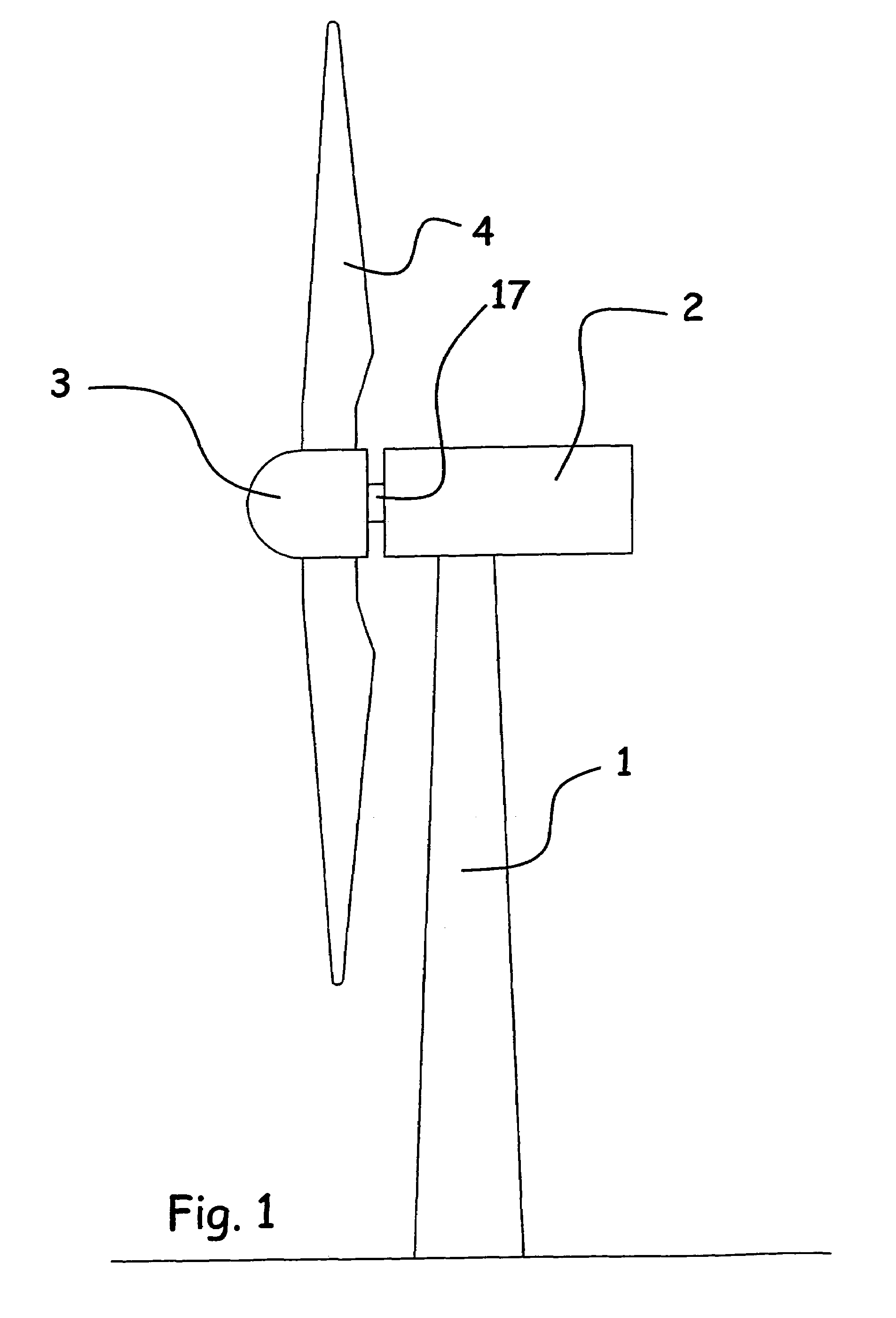
[0045]FIG. 1 shows a wind turbine where a nacelle / turbine top section 2 is conventionally mounted on the tower 1, a generator and a gear being mounted in said nacelle. A rotor shaft 17 projects from the nacelle 2, the rotor hub 3 of the wind turbine being mounted on said rotor shaft. The blades 4 of the wind turbine are mounted on the rotor hub 3.

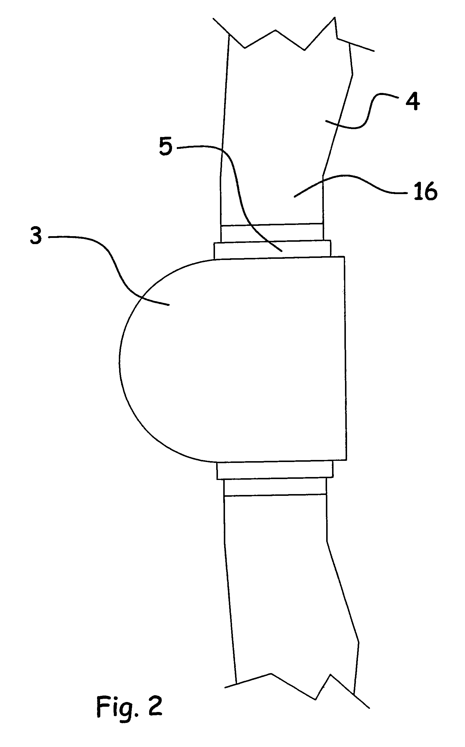
[0046]FIG. 2 shows a detailed view of a rotor hub 3 for a wind turbine as well as portions of two blades 4. In the structure shown, the blades 4 and the rotor hub 3 are connected through pitch bearings 5, and the position of the blades 4 is adjustable about their longitudinal axes, i.e. the pitch angle, by means of said bearings.

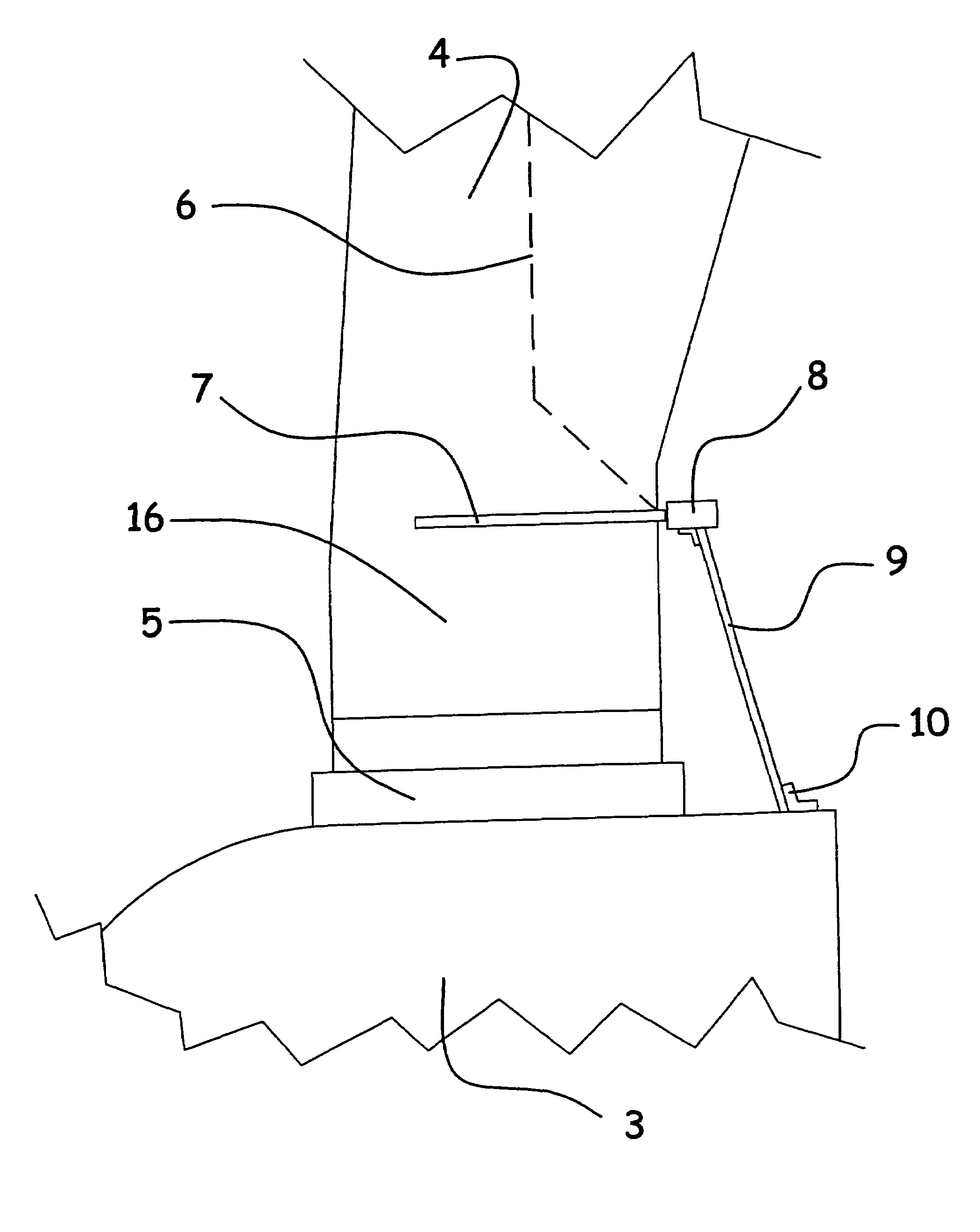
[0047]In order to intercept and guide a lightning strike to the ground, an inner lightning down-conductor 6 is mounted inside the blade 4, cf. FIG. 3, said lightning down-conductor being connected at the tip of the blade 4 to one or more lightning receptors not shown. Adjacent the pitch bearing 5, this inner lightni...


PUM


Abstract

A wind turbine rotor including a rotor hub (3) and a plurality of blades (4), and where each blade root (16) is connected to said rotor hub through a pitch bearing (5) in such a manner that the pitch angle of the blade is adjustable by a turning of the blade about its longitudinal axis relative to the rotor hub. The blade is provided with at least one electrically conducting lightening down-conductor (6) extending in the longitudinal direction of the blade to the blade root and being electrically isolated from the pitch bearing (5). A spark gap (15) is provided between the lightning down-conductor and the rotor hub, said spark gap (15) being adapted to conduct a lightning current passing through the lightning down-conductor. A sliding contact connection (7, 12) is provided parallel to the spark gap (15) between the lightning down-conductor (6) and the rotor hub (3), said sliding contact connection ensuring electrical contact between said lightening down-conductor (6) and said rotor hub (3) irrespective of the pitch angle of the blade. The invention also relates to a wind turbine including such a rotor.

Description

TECHNICAL FIELD[0001]The invention relates to a wind turbine rotor including a rotor hub and a plurality of blades, and where each blade root is connected to said rotor hub through a pitch bearing in such a manner that the blade is pivotable about its longitudinal axis relative to the rotor hub, and where said blade is provided with at least one electrically conducting lightening down-conductor extending in the longitudinal direction of the blade to the blade root and being electrically isolated from the pitch bearing, and where a spark gap is provided between the lightning down-conductor and the rotor hub, said spark gap being adapted to conduct a lightning current passing through the lightning down-conductor.[0002]Furthermore, the invention relates to a wind turbine with the above wind turbine rotor.BACKGROUND ART[0003]It is common knowledge that wind turbines are protected against lightning strikes, and it is also common knowledge that wind turbine blades are provided with lightn...

Claims


Application Information

Patent Timeline
Patent Type & Authority Patents(United States)
IPC IPC(8): F03D9/00F03D11/00H02G13/00
CPCF03D11/00F03D11/0033H02G13/00H02G13/40H02G13/80Y02E10/722Y02E10/721F03D80/00F03D80/30F03D80/70Y02E10/72
Inventor LARSEN, FLEMMING MOLLERHANSEN, LARS BO
Owner LM GLASSFIBER
Why Eureka
Try Eureka