Weft yarn brake for loom

A technology of brakes and weft yarns, which is applied in looms, textiles, textiles and papermaking, etc., can solve the problems of easy torn weft yarns and the possibility of brake adjustment not being fully satisfactory

Inactive Publication Date: 2005-06-01
L G L ELECTRONICS
View PDF0 Cites 0 Cited by
  • Summary
  • Abstract
  • Description
  • Claims
  • Application Information

AI Technical Summary

Problems solved by technology

[0008] Conventional dedicated weft brakes, which have very good performance in terms of braking action, but these brakes have some disadvantages, especially the possibility of brake adjustment which is not fully satisfactory
[0009] Furthermore, the weft yarn brake is extremely prone to tearing the weft yarn, especially if there are uneven parts, such as knots or weak parts of the weft yarn

Method used


Image

  • Weft yarn brake for loom
  • Weft yarn brake for loom
  • Weft yarn brake for loom

Examples


Embodiment Construction

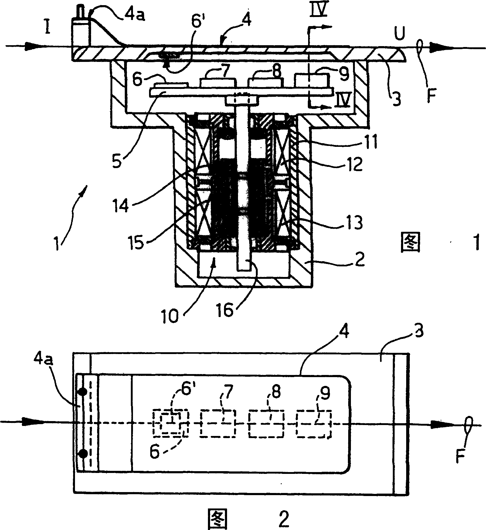
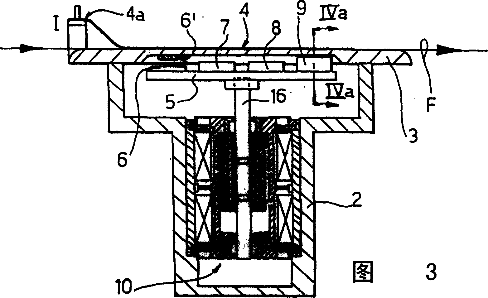
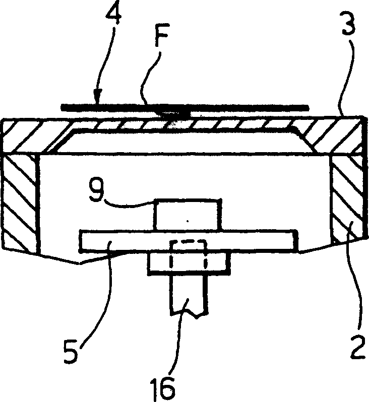
[0028] See Figure 1 to Figure 4 , Reference numeral 1 generally designates a weft thread brake which essentially comprises a hollow body 2 with a flat rigid top plate 3 rigidly connected to the body 2 at its end. The top plate 3 is made of a non-magnetic material such as aluminum and supports a resilient sheet 4 made of a magnetic material such as resilient steel. The foil 4 preferably has an end 4a rigidly connected to the top plate 3, the other end of which is free to move, between which the weft thread F, subject to a regulated braking action, slides. Generally, the connecting end 4a of the sheet 4 is placed at the entrance of the brake, and the end of the mountain is placed at the outlet U of the brake.

[0029] To produce an adjustable braking action, a yoke 5 which is movable linearly and supports a plurality of permanent magnets 6, 7, 8 and 9 is placed under the fixed plate 3 so that the magnets generate magnetic lines of force which pass through the fixed plate and C...


PUM


Abstract

A weft yarn brake (1), especially for looms, comprising a rigid fixed plate (3) of non-magnetic material and an elastic sheet (4) of magnetic material, between which a weft yarn (F) slides; elastic The lamella (4) acts on a rigid fixed plate (3) through permanent magnets (6, 7, 8 and 9) supported by a moving yoke (5) belonging to an electric actuator (10), the electric The actuating device (10) moves the yoke (5) relative to the sheet (4), moving the magnet towards or away from the sheet to change the attractive force of the magnet on the sheet (4) and thus the pressure of the sheet on the weft (F) .

Description

technical field [0001] The present invention relates to a weft brake, in particular a weft brake for looms and the like. Background technique [0002] As is known, the weft thread is fed to the loom by unwinding from a bobbin located in front of a weft feeder from which the weft thread is fed to the loom and other textile machines. [0003] The electric weft brake is generally inserted between the bobbin and the weft feeder and between the weft feeder and the loom, and is used to adjust the mechanism tension of the weft yarn to meet the weaving requirements. [0004] Adjustment of the braking action can be achieved by several traditional methods, in particular by passing the weft thread through two laminar elements, one movable and the other fixed, and by varying the mechanical pressure that presses the movable element against its corresponding fixed element to adjust. [0005] Alternatively, both the fixed element and the movable element are made in the form of combs with...

Claims


Application Information

Patent Timeline
Patent Type & Authority Patents(China)
IPC IPC(8): D03D47/34B65H59/22
CPCB65H59/22B65H2555/13B65H2701/31D03D47/34
Inventor P·塞农G·佩德里恩R·卡斯泰利
Owner L G L ELECTRONICS
Why Eureka
Try Eureka