Power conversion device
A power conversion device, voltage technology, applied in the direction of output power conversion device, electrical components, conversion equipment for intermediate conversion to DC conversion, etc., can solve complex circuit structure, no AC input terminal power factor improvement and current waveform improvement And other issues
- Summary
- Abstract
- Description
- Claims
- Application Information
AI Technical Summary
Problems solved by technology
Method used
Image

Examples
Embodiment 1
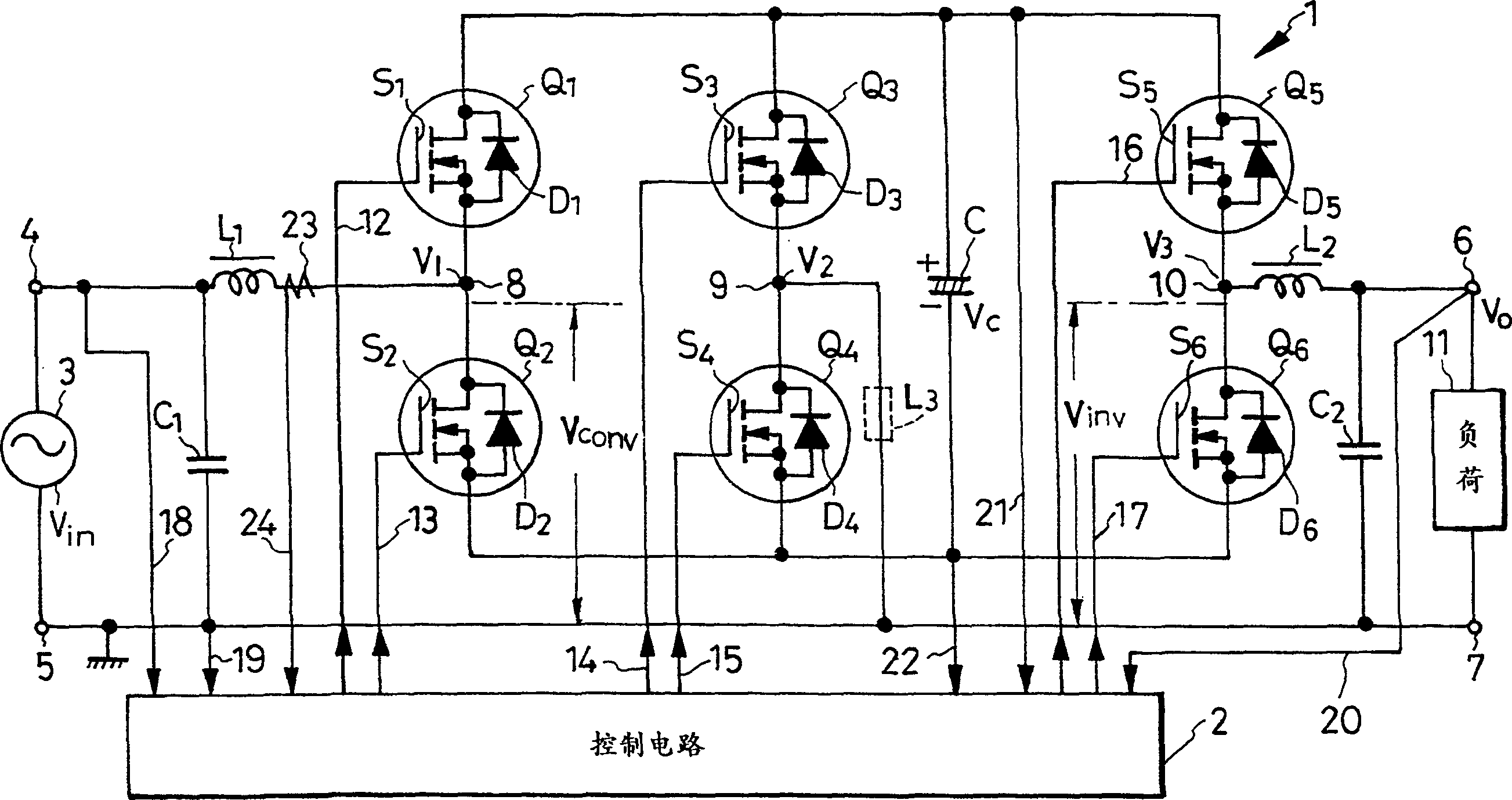
[0054] figure 1 According to Embodiment 1 of the present invention, a switch-type AC-DC-AC device, that is, a power conversion device that can obtain a plurality of voltage conversion forms is shown. This power conversion device can also be referred to as a voltage regulator with a power factor improvement function, and is roughly composed of a conversion circuit 1 and a control circuit 2 .
[0055] The conversion circuit 1 is composed of, for example, an AC input terminal 4 connected to one end of a 50 Hz commercial AC power supply 3, an input-side common terminal 5 connected to the other end of the AC power supply 3, first, second, third, fourth, and fifth and sixth switches Q1, Q2, Q3, Q4, Q5, and Q6, a DC link capacitor composed of polarized electrolytic capacitors or a smoothing capacitor C that can also be called a DC capacitor, an inductor L1 that is a reactance coil of the input stage, and an output stage Inductor L2 is the reactance coil for filtering, capacitor C1 f...
Embodiment 2
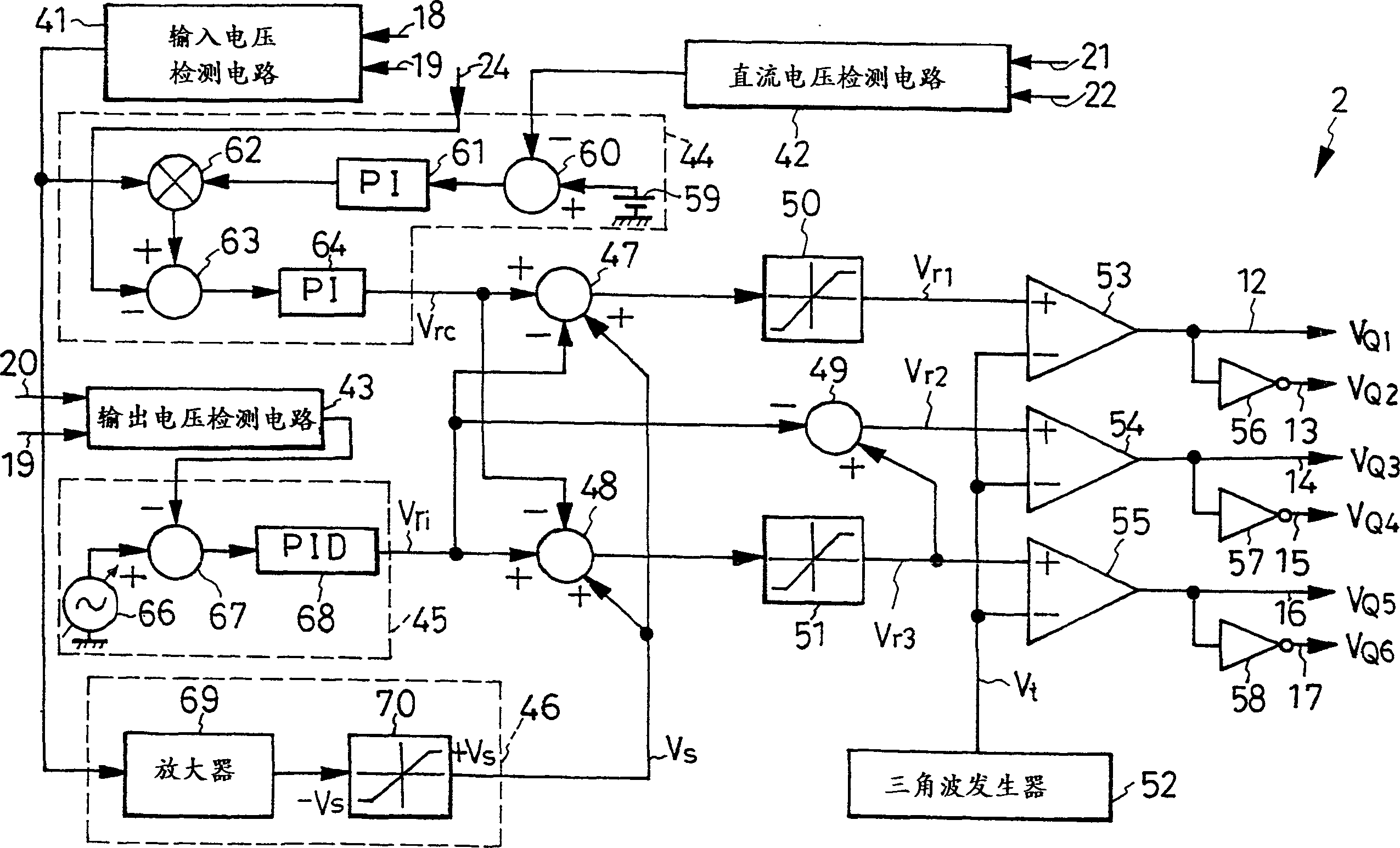
[0142] Below, refer to Figure 13 The voltage converting device of the second embodiment will be described. But when Figure 13 in, for and figure 2 The same symbols are assigned to the same parts, and descriptions thereof are omitted. In addition, in Example 2, refer to Figure 1 to Figure 11 .
[0143] The voltage conversion device of embodiment 2 will figure 1 The control circuit 2 is transformed into Figure 13 shown in control circuit 2a, other configurations and figure 1 same. Figure 13 The control circuit 2a sets the figure 2 The 1st, 2nd and 3rd computing circuits 47a, 48a, 49a after the modification of the 1st, 2nd and 3rd computing circuits 47, 48 and 49 of the control circuit 2, other structures and figure 2 same.
[0144] Figure 13 The first calculation circuit 47a is connected to the first and second command value generation units 44, 45, performs the calculation of the following formula, and outputs the difference signal ΔV. which is
[0145] ...
Embodiment 3
[0160] Below, refer to Figure 14 The control circuit 2b of the voltage conversion device of the third embodiment will be described. But when Figure 14 in, for and figure 2 Parts that are actually the same are denoted by the same symbols, and descriptions thereof are omitted. Figure 14 The control circuit 2b sets the figure 2 The first and second arithmetic circuits 47b, 48b and selection circuit 49b after the deformation of the first, second and third arithmetic circuits 47, 48, 49 of the control circuit 2, in addition, two adders 71, 73 are also provided and a subtractor 72 and the third limiter 74, other structures and figure 2 same.
[0161] Figure 14 The first arithmetic circuit 47b is connected to the first and second command value generation units 44, 45, performs the calculation of Vrc-Vri, and outputs the difference signal ΔV1.
[0162] The second calculation circuit 48b is connected to the first and second command value generation units 44 and 45, perfor...
PUM
 Abstract
Description
Claims
Application Information
 - R&D Engineer
- R&D Manager
- IP Professional
- Industry Leading Data Capabilities
- Powerful AI technology
- Patent DNA Extraction
Browse by: Latest US Patents, China's latest patents, Technical Efficacy Thesaurus, Application Domain, Technology Topic.
© 2024 PatSnap. All rights reserved.Legal|Privacy policy|Modern Slavery Act Transparency Statement|Sitemap