Surface mounted antenna, its making process and radio communicator with the antenna

A surface-mounted antenna technology, applied to antennas, slot antennas, antenna components, etc., can solve problems such as poor work efficiency, small surface-mounted antennas, and resonance frequency errors of radiating electrodes

Inactive Publication Date: 2005-06-22
MURATA MFG CO LTD
View PDF0 Cites 0 Cited by
  • Summary
  • Abstract
  • Description
  • Claims
  • Application Information

AI Technical Summary

Problems solved by technology

[0003] However, the substrate of the surface mount antenna is very small, and conventionally, radiation electrodes have been independently formed one by one on such a small substrate, so there is a problem that the work efficiency is poor and the manufacturing cost of the surface mount antenna is high.
[0004] In addition, there are subtle differences in the dielectric constant and size of the dielectric matrix, which sometimes cause errors in the resonance frequency of the radiation electrode
In order to suppress such an error in the resonant frequency of the radiation electrode, it is necessary to consider the dielectric constant and size of the substrate, and adjust the shape of the radiation electrode with high precision. However, since the radiation electrode is very small, it is necessary to adjust the shape of the radiation electrode with high precision. very difficult
[0005] In addition, when changing the resonance frequency of the radiation electrode of the surface mount antenna, there is a problem that the shape and size of the radiation electrode and the size of the dielectric substrate must be redesigned, which requires a lot of time and labor.

Method used


Image

  • Surface mounted antenna, its making process and radio communicator with the antenna
  • Surface mounted antenna, its making process and radio communicator with the antenna
  • Surface mounted antenna, its making process and radio communicator with the antenna

Examples


Embodiment Construction

[0020] An example of an embodiment of the present invention will be described below with reference to the drawings.

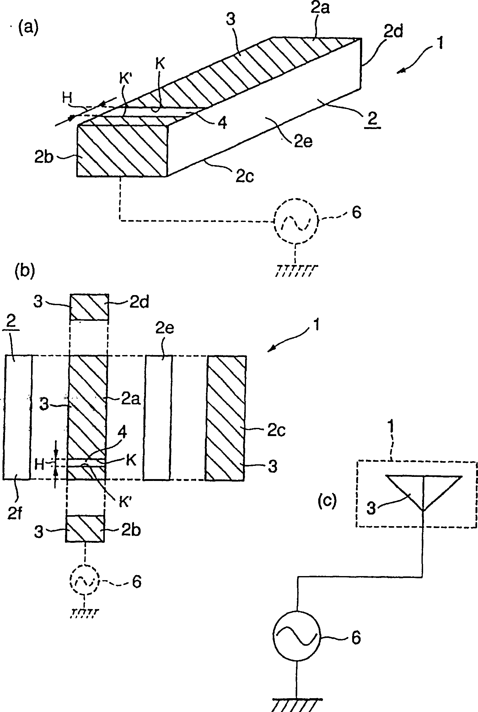
[0021] exist figure 1 In (a), a characteristic surface mount type antenna in the radio communication device of the example of the first embodiment is schematically shown in perspective view, figure 1 (b) shown as figure 1 (a) Expanded view of the surface-mounted antenna shown. In addition, there are various structures of the radio communication device. According to the example of the first embodiment, any structure other than the surface-mounted antenna of the radio communication device can be adopted, and the structure other than the surface-mounted antenna is omitted here. Description of the structure of the radio communication machine.

[0022] In this example of the first embodiment, the characteristic surface mount antenna 1 has a cuboid (thin rectangular) substrate 2 made of a dielectric, and four continuous surfaces of the substrate 2, that is, a fron...


PUM


Abstract

The surface mount type antenna in which a radiation electrode having a predetermined resonant frequency is formed on a substrate can be easily manufactured. Electrodes (11) are formed on the entire surface (10a), end surface (10b), back surface (10c) and end surface (10d) of four continuous surfaces of a dielectric substrate (10). Cutting is then performed with a cutting machine to form a slit (4) intersecting the direction α connecting the end surface (10b) and the end surface (10d) on the electrode (11) on the surface (10a) of the dielectric substrate (10). Then, the dielectric substrate (10) is cut into multiple pieces along the α direction to make multiple surface-mounted antennas (1) approximately surrounded by the radiation electrodes (3) formed on the rectangular parallelepiped base (2). A plurality of surface mount antennas (1) can be produced at one time. The shape of the radiation electrode (3) (electrode 11) is simple, and the cutting machine can be processed with high precision. Therefore, by cutting the narrow slit (4) with a cutting machine, the radiation electrode (3) having a set resonance frequency can be easily formed. ).

Description

technical field [0001] The present invention relates to a surface mount type antenna which can be mounted on a printed circuit board of a radio communication device, its manufacturing method, and a radio communication device having the antenna. Background technique [0002] An antenna that can be surface mounted on a printed circuit board of a radio communication device (surface mount antenna), for example, has a sheet-shaped substrate (such as a dielectric substrate) and a radiation electrode formed on the substrate and capable of receiving and transmitting signals (radio waves). And constitute. Such a surface-mount antenna can be manufactured by, for example, a manufacturing method in which electrodes are formed on a sheet-like base by electroplating, and the electrodes are etched and processed into a predetermined shape to form radiation electrodes. Alternatively, a surface-mount antenna can also be produced by printing a thick-film electrode paste on the surface of the ...

Claims


Application Information

Patent Timeline
Patent Type & Authority Patents(China)
IPC IPC(8): H01P11/00H01Q1/22H01Q1/24H01Q1/38H01Q13/10
CPCH01Q1/2283H01Q1/243H01Q1/38H01Q13/10
Inventor 櫛比裕一
Owner MURATA MFG CO LTD
Why Eureka
Try Eureka