Raman gain real time dynamic control and compensation method and its Raman optical-fibre amplifier

A fiber amplifier and Raman amplifier technology, which is applied in the field of Raman gain real-time dynamic control and compensation, and Raman gain locking, can solve the problems of increasing fiber loss coefficient and decreasing Raman gain, etc. Realize the effect of simple optical path structure

Inactive Publication Date: 2005-06-29
GUANGXUN SCI & TECH WUHAN
View PDF0 Cites 1 Cited by
  • Summary
  • Abstract
  • Description
  • Claims
  • Application Information

AI Technical Summary

Problems solved by technology

However, in the practical application of distributed Raman fiber amplifiers, considering the influence of factors such as the aging of the fiber over time and the change of the ambient temperature, the loss coefficient of the fiber will increase, thereby reducing the Raman gain.

Method used


Image

  • Raman gain real time dynamic control and compensation method and its Raman optical-fibre amplifier
  • Raman gain real time dynamic control and compensation method and its Raman optical-fibre amplifier
  • Raman gain real time dynamic control and compensation method and its Raman optical-fibre amplifier

Examples


Embodiment approach 1

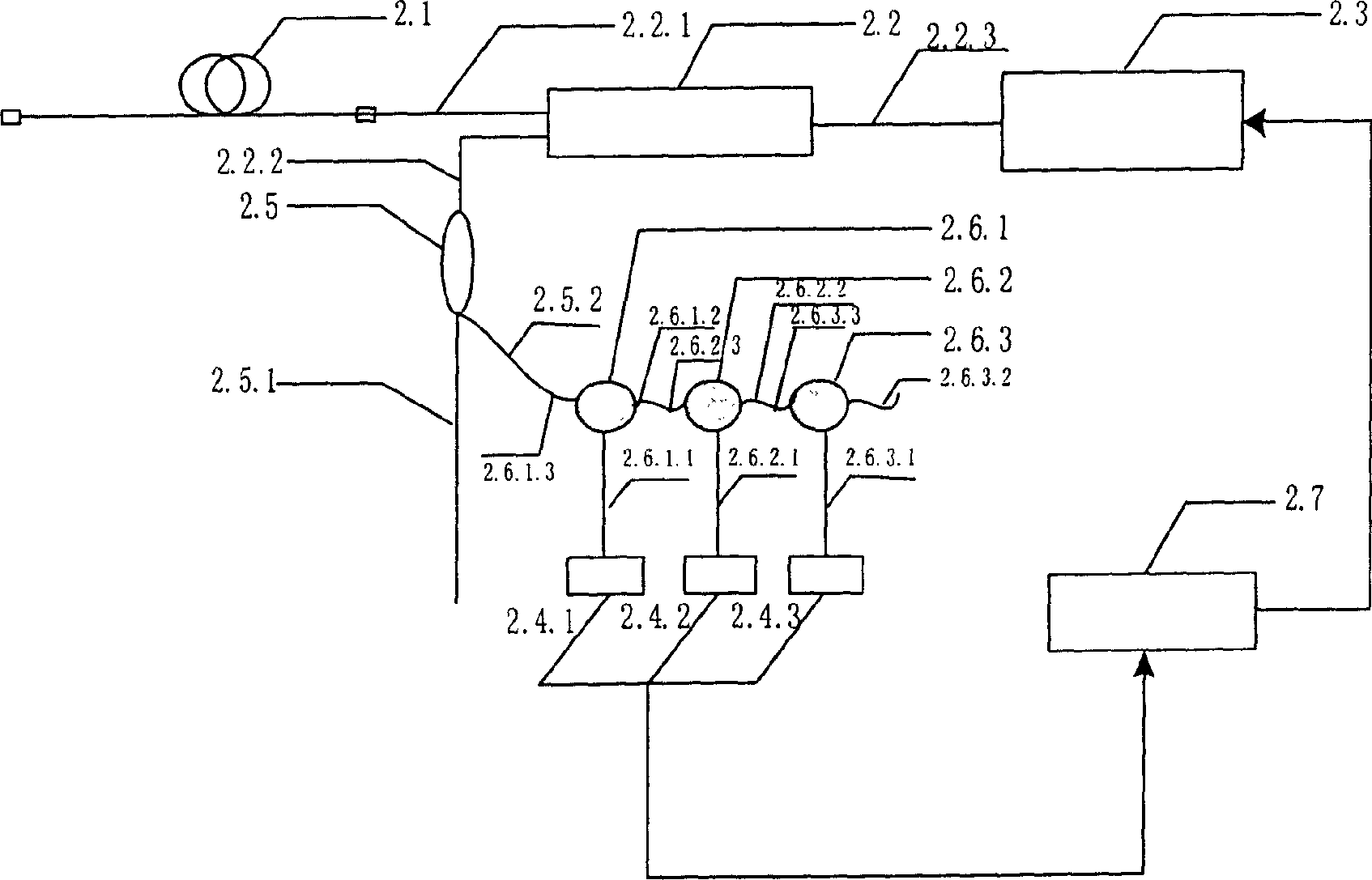
[0039] Embodiment 1 such as figure 2 : According to the optical path structure we designed, only by measuring the backward ASE power at points near the three signal wavelengths (but not coincident with the signal frequency), the automatic control of the Raman gain of the Raman amplifier within the entire amplification bandwidth can be realized and compensation. Band-pass filter 1 is used to detect the ASE optical power within a certain bandwidth with the center frequency v1; band-pass filter 2 is used to detect the ASE optical power within a certain bandwidth with the center frequency v2; band-pass filter 3 is used to detect The center frequency is v3, and the ASE optical power within a certain bandwidth. The center frequency and bandwidth of the bandpass filter are not fixed, as long as it is not the frequency of ITU-T, and it should be designed according to the specific situation.

Embodiment approach 2

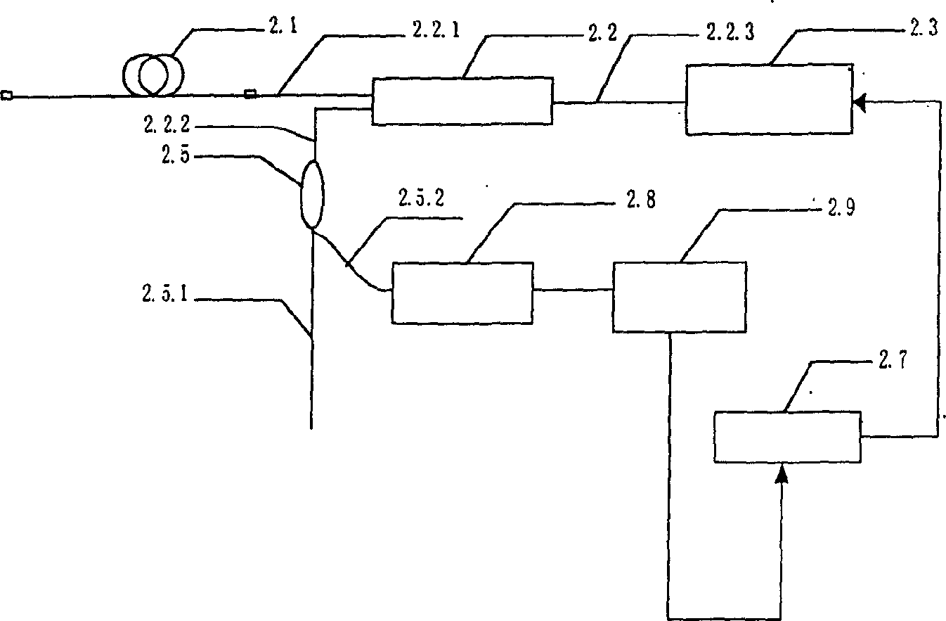
[0040] Embodiment 2 such as image 3 : It is used to detect the backward ASE power of Raman fiber amplifiers at different frequencies by combining tunable optical filters and optical detectors.

[0041]According to the detected ASE power level, the Raman amplifier calculates the Raman gain of each point through the control unit, and automatically adjusts the power level of its pump to keep the ASE power of each point at the required level, thereby realizing the Raman amplifier gain. Real-time dynamic adjustment and control.

[0042] It can be known from theoretical derivation and experimental results that when the ASE power at each point is constant, the Raman gain at this point is uniquely determined, so the power of the pump laser can be easily adjusted automatically through the control unit of the Raman amplifier Keep the ASE optical power at the corresponding center frequency constant or change within a small range, so as to realize the automatic control and compensation ...


PUM


Abstract

The present invention mainly utilizes the spontaneous raidation noise of backward pump, i.e. light power level of ASE to implement autoamtic control of Raman gain of Raman optical-fibre amplifier andcompensation. Its Raman optical-fibre amplifier is characterized by that at the signal light detection place a combination of filter and photoelectric detector for detecting the backward ASE power ofRaman optical fibre amplifier nearby dirrerent wavelength is added, the output of the photoelectric detector is connected with control unit of automatic regulation of gain of Raman amplifier.

Description

technical field [0001] The invention relates to a method for real-time dynamic control and compensation of Raman gain and a Raman fiber amplifier thereof, in particular to the optical path structure design of the Raman fiber amplifier in the field of optical communication and the Raman gain locking of the amplifier. Background technique [0002] If a weak signal and a strong pump light wave are transmitted in the fiber at the same time, and the wavelength of the weak signal is placed within the Raman gain bandwidth of the pump light, the weak signal light can be amplified. This mechanism is based on stimulated Raman scattering. The optical amplifier is called Raman fiber amplifier. The gain spectrum of a Raman fiber amplifier is determined by the wavelength of the pump laser and the properties of the fiber. Under the condition of a single pump wavelength of 1455nm, the basic shape of the Raman gain spectrum in G.652, G.655 (Leaf), DCF fiber is as follows figure 1 shown. I...

Claims


Application Information

Patent Timeline
Patent Type & Authority Patents(China)
IPC IPC(8): G02F1/39H01S3/30
Inventor 印新达付成鹏
Owner GUANGXUN SCI & TECH WUHAN
Why Eureka
Try Eureka