Clarity enhancement system and method and video-frequency displaying system

A technology to enhance system and definition, applied in the field of video processing, can solve the problems of the processor bus bandwidth requirements cannot be realized, and the process division cannot be realized.

Inactive Publication Date: 2005-07-20
FUNAI ELECTRIC CO LTD
View PDF0 Cites 0 Cited by
  • Summary
  • Abstract
  • Description
  • Claims
  • Application Information

AI Technical Summary

Problems solved by technology

Often, optimal process partitioning cannot be achieved due to bandwidth constraints
For example, in a multimedia processing system, based on the appropriate implementation of each specific task, or to facilitate parallel processing, the preferred partitioning is usually not possible due to the bandwidth requirements it creates on the processor bus.

Method used


Image

  • Clarity enhancement system and method and video-frequency displaying system
  • Clarity enhancement system and method and video-frequency displaying system
  • Clarity enhancement system and method and video-frequency displaying system

Examples


Embodiment Construction

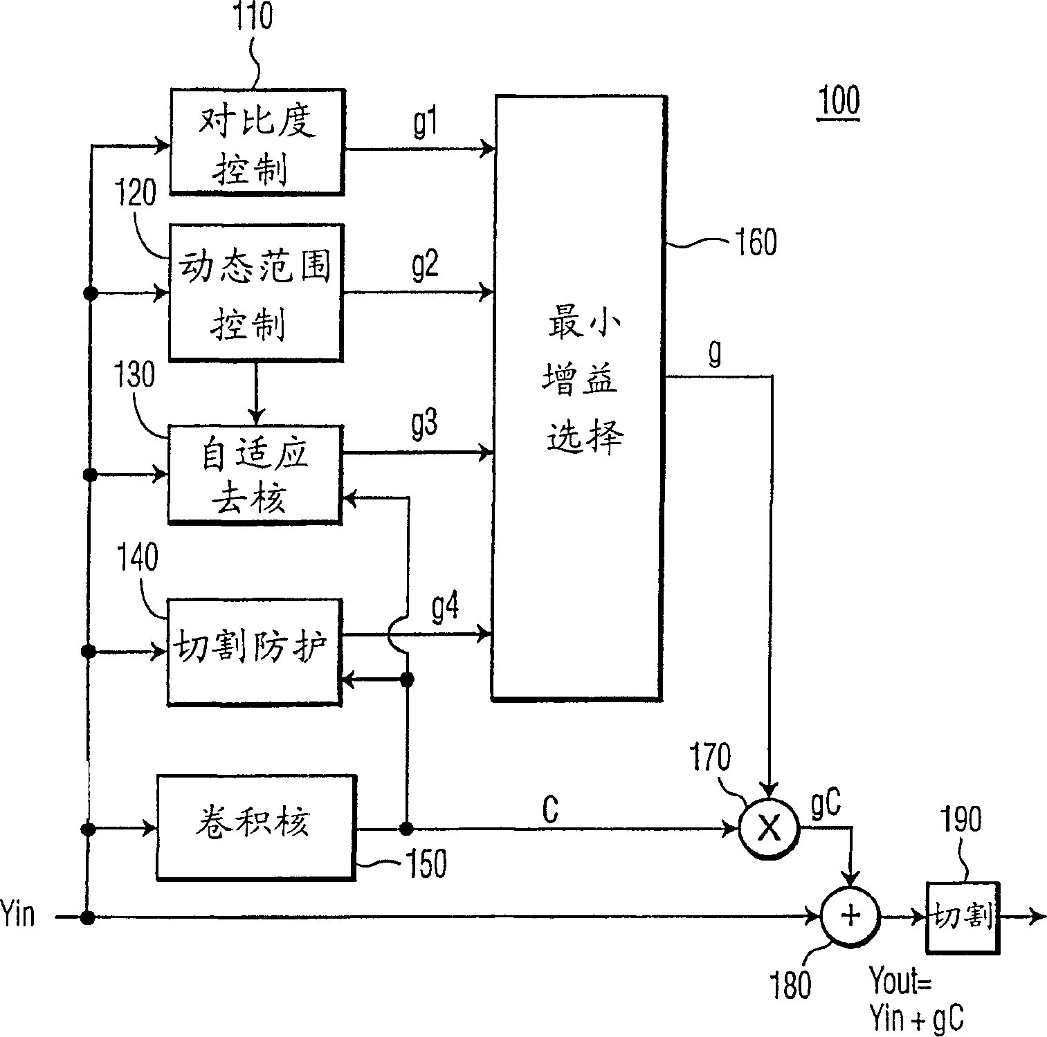
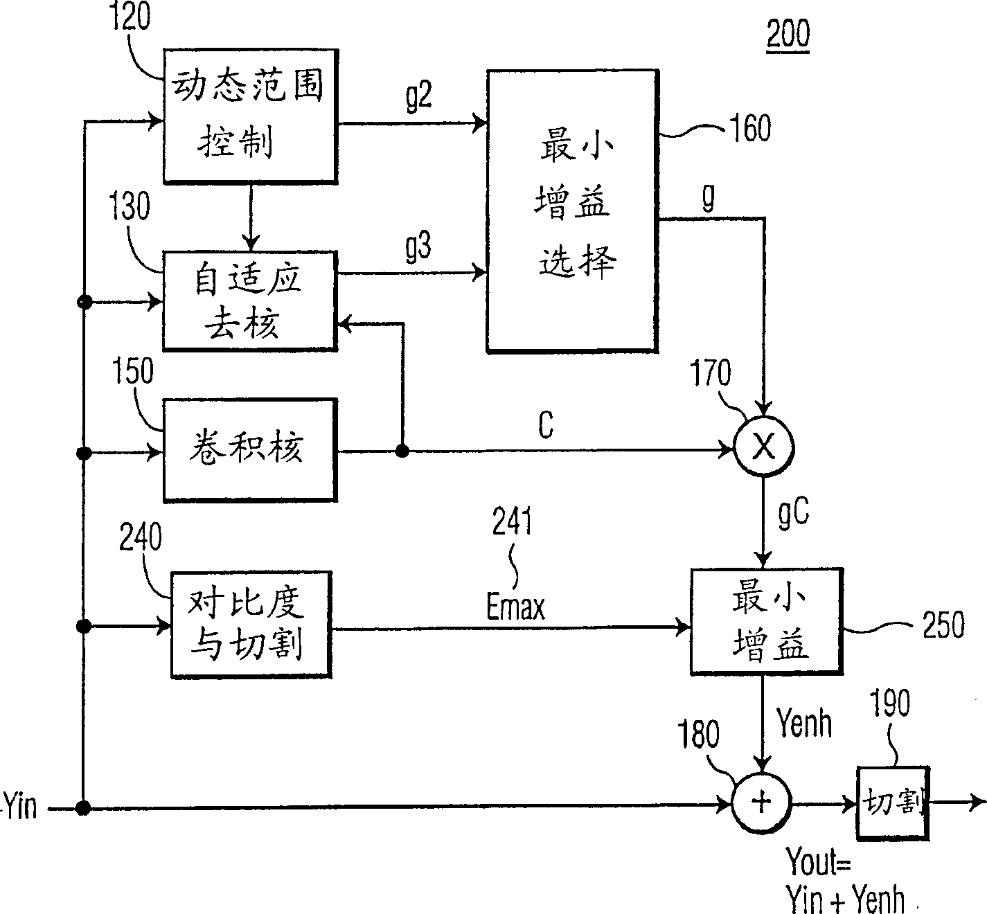
[0042] figure 2 An example block diagram of a picture sharpness enhancement system 200 according to the present invention is shown. As mentioned earlier, shown in figure 1 The contrast control 110 and clipping guard 140 modules of the prior art system 100 often produce contradictory results regarding the maximum gain (g1 and g4, respectively) that may be used to determine the convolution-determined Enhanced (g*C). In a preferred embodiment of the invention, the contrast control and cut protection functions, which are usually independent of each other, are integrated as figure 2 A single contrast and cut protection module in the sharpness enhancement system 200.

[0043] To prevent clipping, enhancements applied to each pixel value should not produce output pixel values ​​outside the allowed range of pixel values. For ease of reference and understanding, it is assumed here that the allowable pixel value range is from 0 to 255, although any other value may be used:

[004...


PUM


Abstract

A contrast control and clipping device is configured to determine a maximum range of enhancement that may be applied to each pixel for picture sharpness enhancement. This maximum range is used to limit the enhancement that is determined by the conventional convolution kernel and gain control modules. Preferably, the maximum range is independent of the determined convolution value, thereby minimizing the bandwidth requirements among the modules used for picture sharpness enhancement. The reduced bandwidth requirement allows for an efficient partitioning of tasks between hardware and software embodiments, and eases the overall system design task. In a multi-media application, the amount of data that is transferred between the processor and sub-components is substantially reduced, and the efficient partitioning facilitates parallel processing. The maximum range of enhancement is determined based on the pixel values in the current field, using a computationally simple algorithm, thereby minimizing anomalies caused by temporal dependencies among the modules that are used for picture sharpness enhancement. Additionally, the sharpness enhancement is dynamically adjusted based on overall picture-level characteristics, including the average enhancement range, overall noise measures, and so on.

Description

technical field [0001] The invention relates to the field of video processing, in particular to methods for enhancing video images. Background technique [0002] The "sharpness" of an image can be improved by enhancing the high frequency components of the image; that is, emphasizing the edges and other parts of an image and sharpening changes rather than gradual transitions. However, high frequency enhancement can cause some changes to be overemphasized, causing "spotting" and other unappealing visual effects in the image. [0003] figure 1 A block diagram of a conventional sharpness enhancement device 100 is shown. The sharpness enhancement device 100 includes a convolution kernel 150, which functions as a high-frequency filter to determine high-frequency components of an image. Generally, an image on a television screen refers to a frame. As used herein, the terms image and frame are used interchangeably and are meant to include all or a portion of a collection of data...

Claims


Application Information

Patent Timeline
Patent Type & Authority Patents(China)
IPC IPC(8): H04N5/208H04N5/66
CPCH04N5/208H04N5/57
Inventor M·巴克穆特斯基J·G·詹森E·G·T·亚斯珀斯
Owner FUNAI ELECTRIC CO LTD
Why Eureka
Try Eureka