
Metal pile head

A metal and pile head technology is applied in the field of special metal pile heads for expanding bottom piles to form piles, which can solve the problems such as the inability to remove the mud at the bottom of the pile and the settlement of the pile, and achieve a low ratio of single pile bearing capacity, low single pile cost, Simple effect of piling process

Inactive Publication Date: 2005-07-27
王国奋
View PDF0 Cites 2 Cited by
  • Summary
  • Abstract
  • Description
  • Claims
  • Application Information

AI Technical Summary

Problems solved by technology

The reason is that the mud at the bottom of the pile cannot be removed, which will lead to the settlement of the pile

Method used


Image

  • Metal pile head
  • Metal pile head
  • Metal pile head

Examples


Embodiment Construction

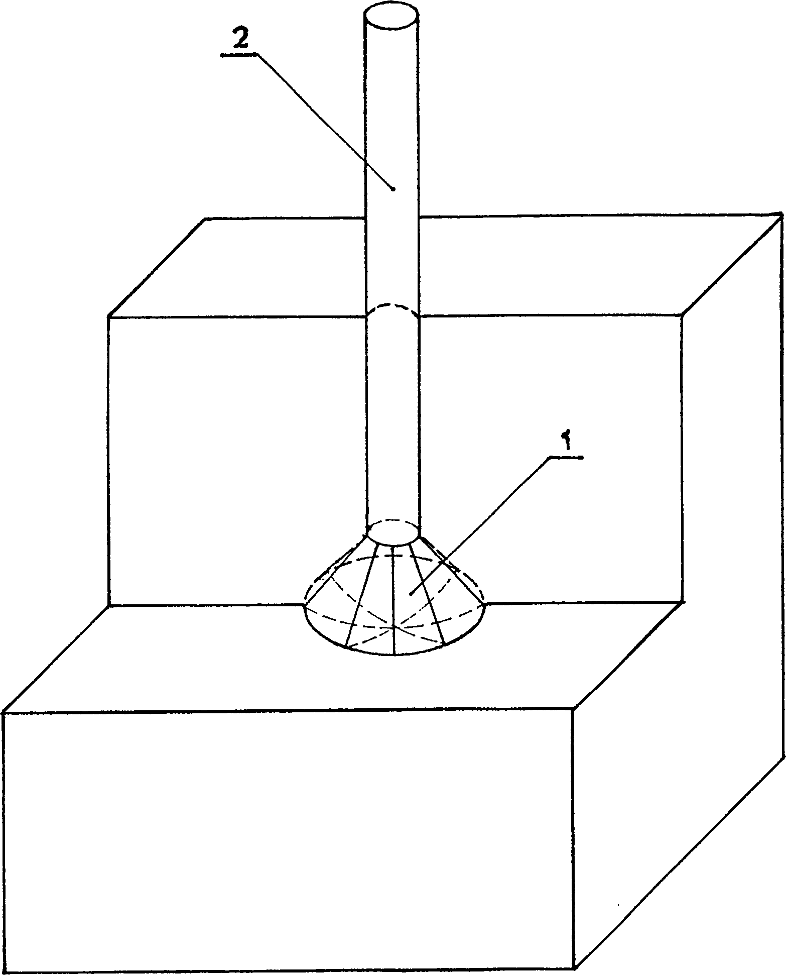
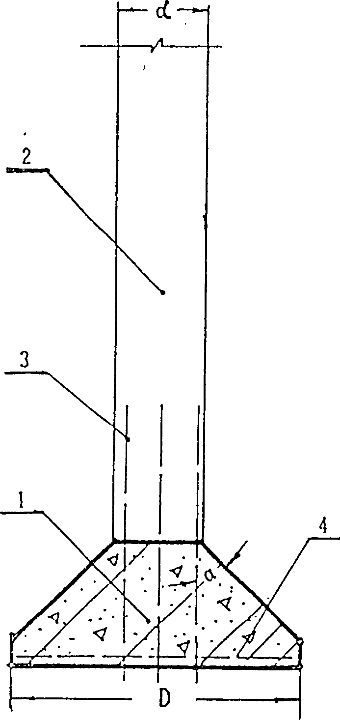
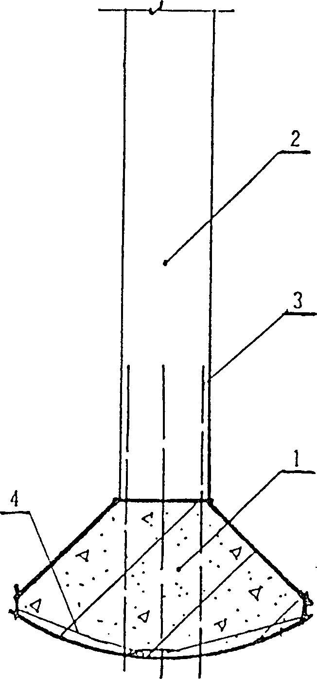
[0038] Such as Figure 1-4 As shown, the immersed tube prefabricated steel concrete expanded bottom pile is composed of a prefabricated pile body 2 and a cast-in-place steel concrete base 1, and the pile body 2 is docked with the base 1 by using the inserted rib 3 at the bottom in the hard soil layer under the positioning of the immersed tube Anchored to form a whole.

[0039] The diameter of the largest part of the base 1 should be greater than the diameter of the pile body 2. Optimally, the cross-sectional diameter d of the pile body 2 is 250-700 mm, and the ratio of the diameter D to d of the largest cross-sectional part of the base 1 is generally 1.5

[0040] The specific shape of the cast-in-place reinforced concrete base 1 is not limited, but tests have shown that if Figure 2~4 The three classes of shapes shown...


PUM


Abstract

The metal pile head set inside the sunken tube features the conic shape with large-headed horizontal pin on the inner wall. By means of the metal pile head, the sunken tube and corresponding piling method, the diameter ratio between the enlarged pedestal and the pile column may reach 1.5, and the routine enlarged pedestal has area up to 2.3 sq m and bearing capacity up to 270 T. Owing to the setting sunken tube, dry soil taking and air sucking, the pedestal enlarging process can clean the bottom of pile to reach the effective factor of 1.00. The existence of the sunken tube can ensure the reliability of the enlarged pedestal, and the bottom may be enlarged sufficiently and accurately.

Description

[0001] This application is a divisional application with the application number of 97105261.1, the application date of 970718, and the name of "immersed tube prefabricated steel concrete expanded bottom pile and its pile forming method and equipment". Technical field: [0002] The invention relates to pile-forming equipment for prefabricated steel concrete expanded-bottom piles with immersed tubes, in particular to a special metal pile head for forming expanded-bottom piles. Background technique: [0003] my country's coastal areas are all soft soil foundations. At present, in the pile foundation engineering of soft soil foundations, three types of piles are generally used: immersed tube piles, prefabricated piles and large diameter bored piles. Among them, the large-diameter bored pile has the highest bearing capacity, but its cost is high, its work efficiency is low, and the pollution is serious during construction. Therefore, it is generally only used in buildings with hi...

Claims


Application Information

Patent Timeline
Patent Type & Authority Patents(China)
IPC IPC(8): E02D5/34E02D5/72
Inventor 王国奋
Owner 王国奋
Learn More