Method for calibrating industrial CT system detector by group series winding

A calibration method and detector technology, which can be used in digital differential analyzers, calculations using non-numerical representations, and material analysis using radiation. Increased computation time, good correction quality, and fewer iterations

Inactive Publication Date: 2005-09-21
TSINGHUA UNIV
View PDF0 Cites 0 Cited by
  • Summary
  • Abstract
  • Description
  • Claims
  • Application Information

AI Technical Summary

Problems solved by technology

[0003] 1) For the method of correcting with direct deconvolution function, because the deconvolution function always has errors, the correction of each set of data is not accurate, so there are still obvious artifacts in the image reconstructed by recombining each set of data , the correction effect is not good
[0004] 2) For the deconvolution iterative method, it is not practical for industrial CT systems with a large amount of data because it needs to be iterated, and generally it takes multiple iterations to achieve the purpose of correction
[0006] 4) For the method of adding the detector cross-winding model in iterative reconstruction, it is currently limited to the correction of general detector cross-winding, and the correction speed is slow, requiring multiple iterations to complete
Moreover, many of the current iterative methods converge very slowly, which is not applicable to the actual system.

Method used


Image

  • Method for calibrating industrial CT system detector by group series winding
  • Method for calibrating industrial CT system detector by group series winding
  • Method for calibrating industrial CT system detector by group series winding

Examples


Embodiment Construction

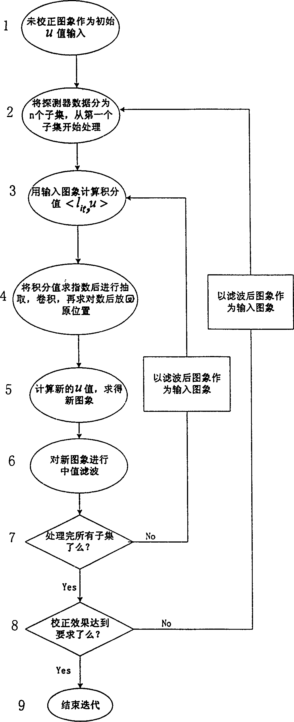
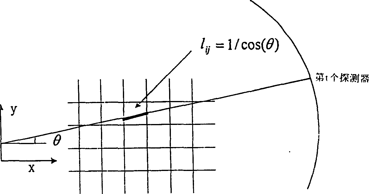
[0025] The specific method for calculating the integral value with the input image as described in step (3) in the technical solution is: set the number of subsets as s, and in a certain projection direction i, input the absorption coefficient Compute the integral value in each detector direction t l it , u n > = Σ j l itj u j n , where l itj is the intersecting length of pixel j in the direction of detector t when projecting direction i; t=1, 2, ..., k, k is a natural number, t is the number of detectors in each scan, and all integrals are calculated for t valueit , u n >, repeat the above step (3) for all i in the subset, and calculate all integral values ​​it , u n >, i=(s-1)*r / n+1,...,s*r / n. The intersection length l itj can be a...


PUM


Abstract

Calibration of industrial CT system inspector by group series winding relates to re-established images. It carries out to process projection data generated by inspector group series winding model based on Ordered Subsets Convex, to make medium filtration after each iteration in order to speed up convergence. This invention needs less times of convergence and has quality calibration.

Description

(1) Technical field [0001] The invention belongs to the field of nuclear technology and uses a mathematical method to correct the reconstructed image of a CT system. (2) Background technology [0002] In the actual industrial CT system, every 8 detectors form a group, and a group of detectors are connected in series, so there are obvious artifacts in the reconstructed image. Currently, there are three main methods for correction of detector cross-winding effects in CT systems: using direct deconvolution function, deconvolution iterative method and adding detector cross-winding model in iterative reconstruction. None of the above-mentioned methods is aimed at the case of packet string winding, and they have the following disadvantages when they are used in our actual CT system detector packet string winding: [0003] 1) For the method of correcting with the direct deconvolution function, because the deconvolution function always has errors, the correction of each set of data...

Claims


Application Information

Patent Timeline
Patent Type & Authority Patents(China)
IPC IPC(8): G01N23/04G06F7/64G06F17/10
Inventor 孙少华高文焕张丽陈志强
Owner TSINGHUA UNIV
Why Eureka
Try Eureka