
Current-limiting device with repulsive force mechanism

A technology of a current limiting device and a repulsive force mechanism, which is applied to the operation/release mechanism of the protection switch, etc., can solve the problems of poor stability of the acting force and large action error of the current limiting device, and achieve equal contact pressure, improved short-circuit breaking ability, and contact high pressure effect

Inactive Publication Date: 2005-10-19
陈臣明 +1
View PDF2 Cites 1 Cited by
  • Summary
  • Abstract
  • Description
  • Claims
  • Application Information

AI Technical Summary

Problems solved by technology

[0003] The present invention mainly solves the technical problems such as relatively large action error and poor stability of the active force in the existing current limiting device.

Method used


Image

  • Current-limiting device with repulsive force mechanism
  • Current-limiting device with repulsive force mechanism
  • Current-limiting device with repulsive force mechanism

Examples


Embodiment

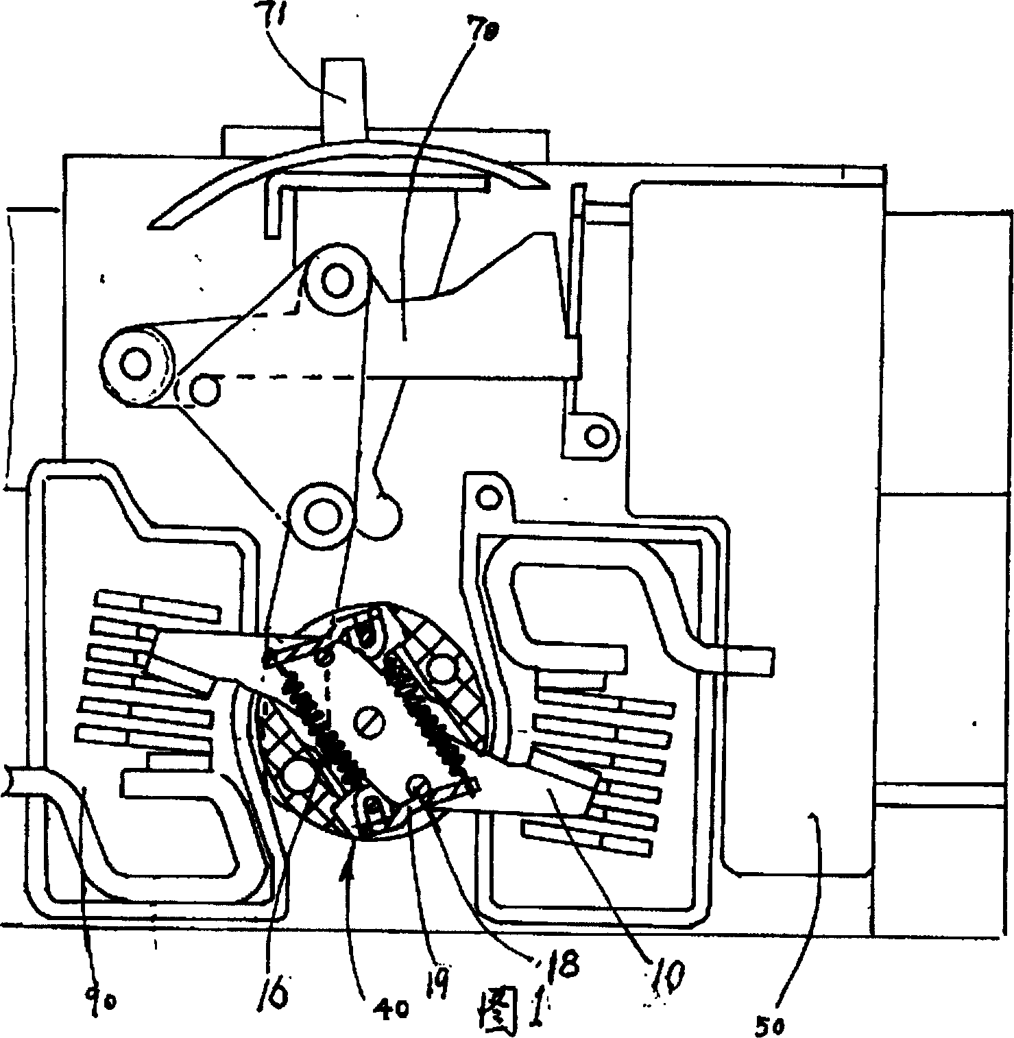
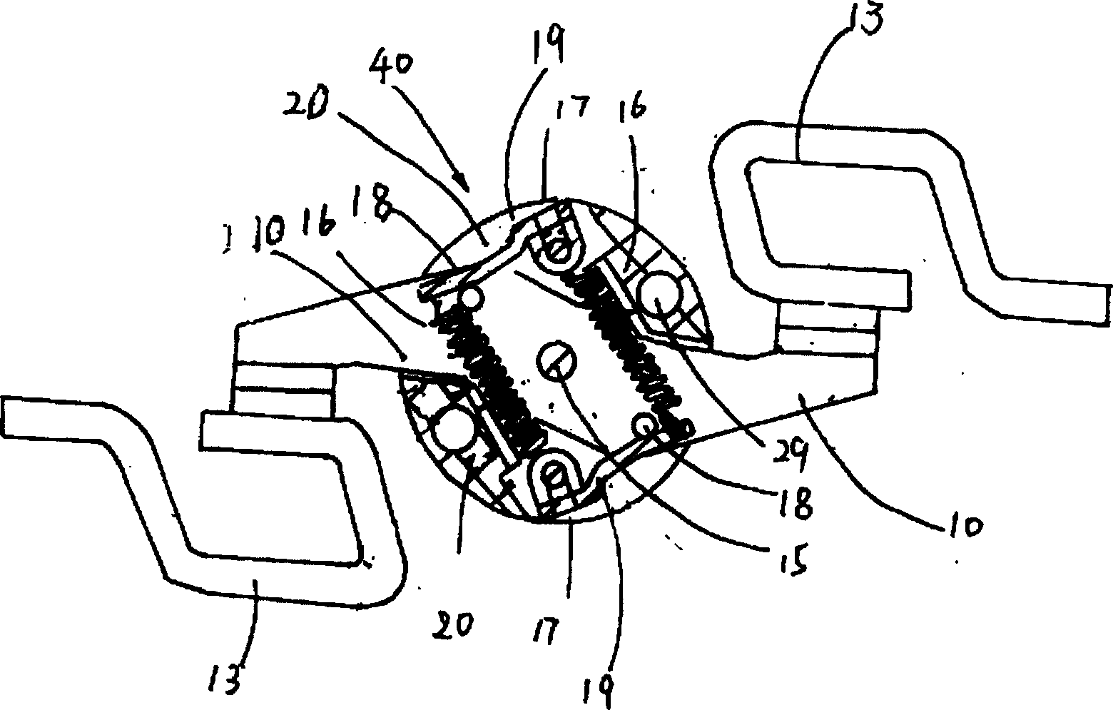
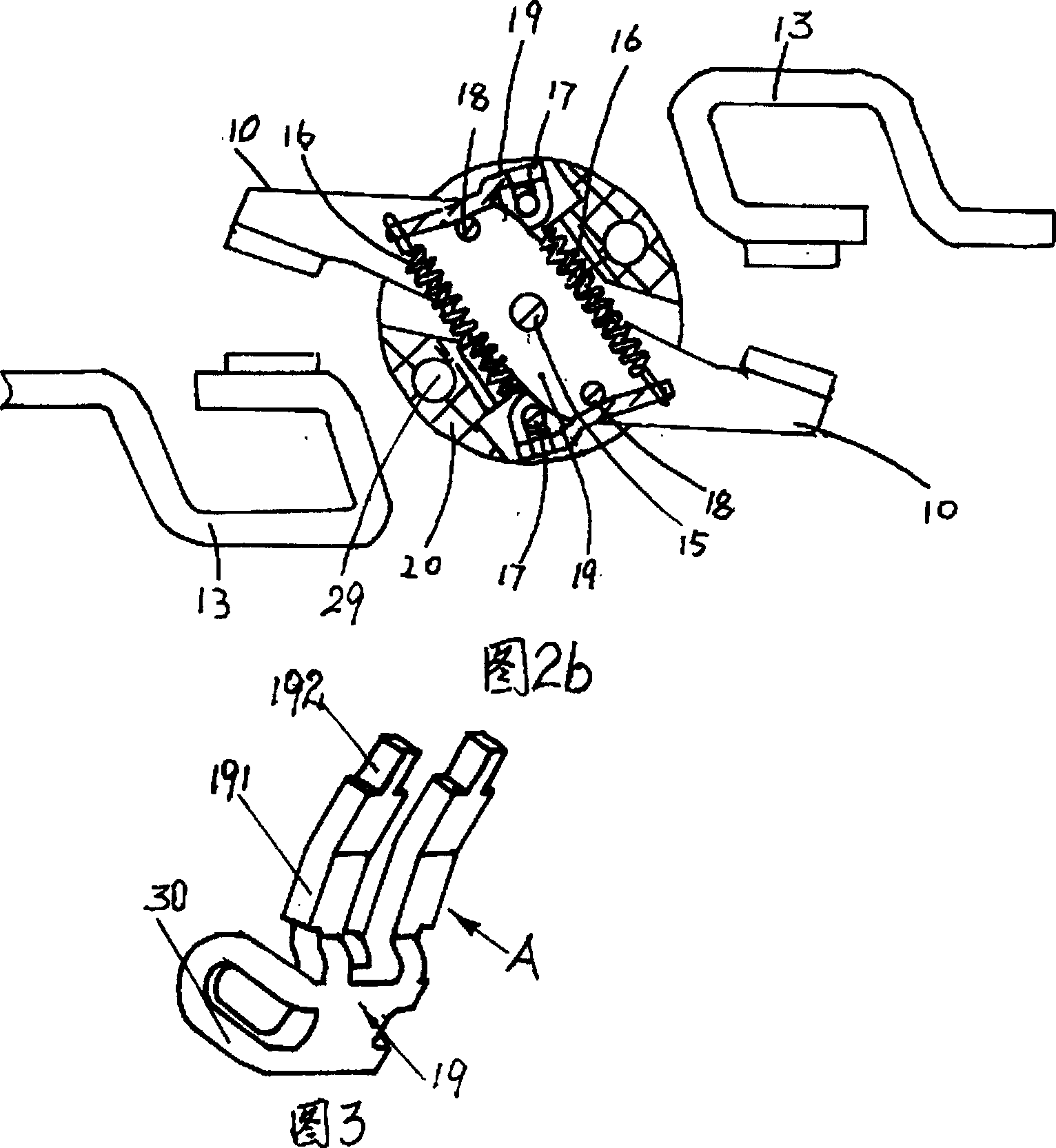
[0018] Embodiment: the current limiting device 40 is provided with a repulsive pin 18 on the movable contact 10, and a repulsive member 19 is placed outside it; the repulsive member 19 is U-shaped and rides on the movable contact On both sides of 10, the two arms 191 of roughly equal width are in a slightly upturned arc shape, and the ends are narrowly inserted into the end circle of the return spring 16; 30, the repulsion member 19 formed thus is made of steel plate as a whole (see accompanying drawing 3 and attached Figure 4 ), and is arranged on the support 20 through the pivot pin 17; and the movable contact 10 is fixed on the support through the central axis 15, so that it can rotate around this axis. A return spring 16 is arranged inside the button body 30 , and the other end of the return spring is arranged at the near-moving contact end 192 of the other repelling member 19 . The end of the repulsion member away from the moving contact is set on the bracket 20 by the ...


PUM


Abstract

The invention relates to the current limiting device with the expulsive force mechanism utilized in the breaker. The expulsive force pin is installed in the moving contact and the expulsive force piece is installed outside the moving contact. The end bent as the fastener swerved from the moving contact of the expulsive force pipe through the axle pin is setup in the bracket. The other end of the expulsive force piece through the back moving spring, which is in the inner side of the fastener, is setup in the bracker. The expulsive force piece in U shape sits on two sides of the moving contact. When the current exceeds the rated current, the expulsive force generated cuts off the circuit effectively, making the moving and static contacts keep good synchronism and equal pressure. The invention provides the features of the simple structure, the fast speed for turning the breaker on as well as the good stability.

Description

technical field [0001] The invention relates to a circuit breaker, in particular to a current limiting device with a repulsive force mechanism for the circuit breaker, so as to greatly improve the capability of breaking short-circuit current and the reliability of breaking. Background technique [0002] When there is an abnormal situation in the electrical device or circuit, the circuit breaker needs to quickly cut off the circuit to prevent damage or fire of the circuit or electrical equipment. This is an important current-limiting performance of the circuit breaker. In order to improve the current-limiting performance of the breaker, the engineering and technical personnel of the relevant electrical appliance manufacturers in various countries have made a lot of efforts. For example, someone applied for an invention patent entitled "Multi-pole circuit breaker with single-pole unit" (92111529.6), which relates to a low-voltage multi-pole circuit breaker with two housings, e...

Claims


Application Information

Patent Timeline
Patent Type & Authority Patents(China)
IPC IPC(8): H01H71/12
Inventor 杨长发张顺发徐醒凡周成伟
Owner 陈臣明
Learn More