Integrated switch with RF transformer control
A technology for controlling circuits and oscillating circuits, applied in circuits, output power conversion devices, transformers/inductor coils/windings/connections, etc., can solve problems such as bulky and expensive
- Summary
- Abstract
- Description
- Claims
- Application Information
AI Technical Summary
Problems solved by technology
Method used
Image

Examples
Embodiment Construction
[0029] The same components in different drawings are marked with the same symbols. For the sake of clarity, only that which is necessary for understanding the invention is shown in the drawings and will be described below. In particular, the circuitry for power switch control is not shown, as that is not the object of the invention. Also not shown are those possible circuits for providing the operating set point at the control circuit inlet to the isolation barrier.
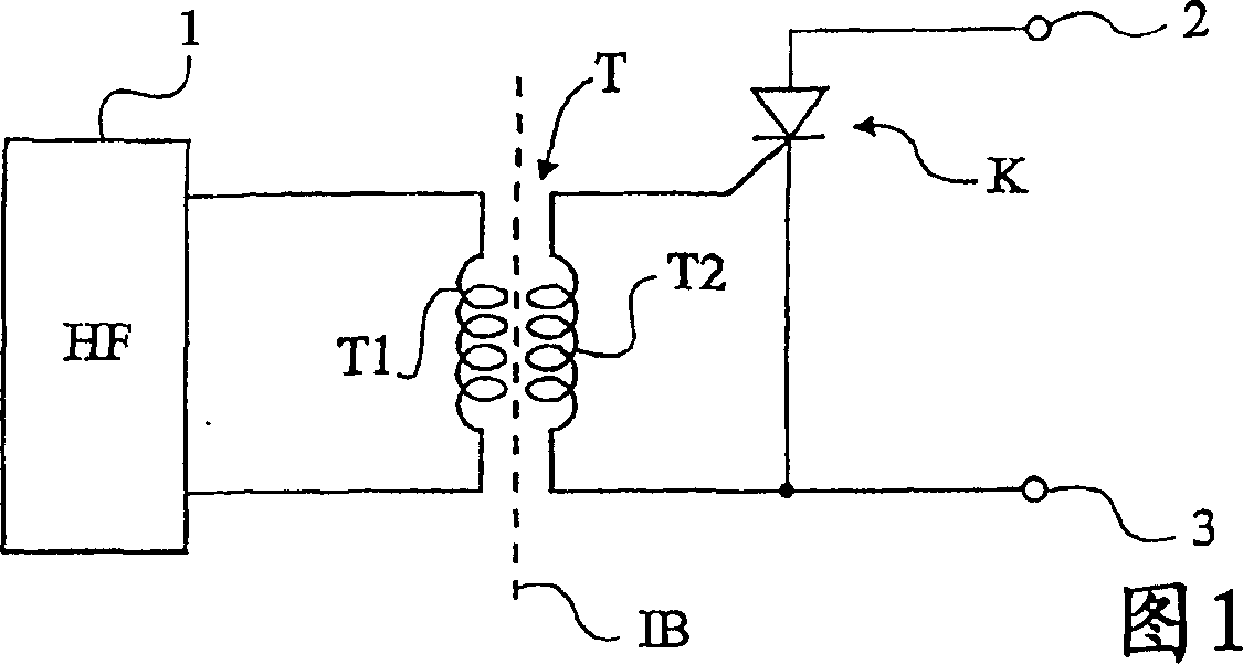
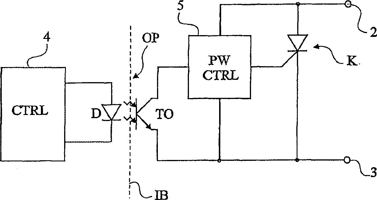
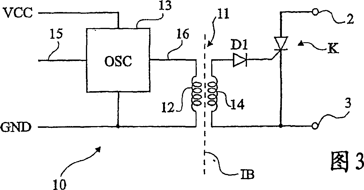
[0030] FIG. 3 shows an embodiment of a control circuit 10 of a power switch K with an electrical isolation barrier (barrier IB). The content of Figure 3 should be compared with that of traditional Figures 1 and 2.
[0031] According to the invention, a very high frequency (at least tens of MHz) transformer 11 is used, which has a primary winding 12 controlled by a circuit 13 (OSC), a secondary winding 14 for controlling the power at the outlet of the isolation barrier IB Switch K. As mentioned above, the swit...
PUM
| Property | Measurement | Unit |
|---|---|---|
| capacitance | aaaaa | aaaaa |
| conversion efficiency | aaaaa | aaaaa |
Abstract
Description
Claims
Application Information
 - R&D
- Intellectual Property
- Life Sciences
- Materials
- Tech Scout
- Unparalleled Data Quality
- Higher Quality Content
- 60% Fewer Hallucinations
Browse by: Latest US Patents, China's latest patents, Technical Efficacy Thesaurus, Application Domain, Technology Topic, Popular Technical Reports.
© 2025 PatSnap. All rights reserved.Legal|Privacy policy|Modern Slavery Act Transparency Statement|Sitemap|About US| Contact US: help@patsnap.com