Leakage circuit breaker

A leakage circuit breaker and main circuit technology, applied in electromagnetic release switches, switches with multiple unbalanced current/voltage effects, protection switch operation/release mechanisms, etc. The effect of reducing the number of parts, saving space, and stable opening characteristics

Inactive Publication Date: 2006-02-01
MATSUSHITA ELECTRIC WORKS LTD
View PDF1 Cites 0 Cited by
  • Summary
  • Abstract
  • Description
  • Claims
  • Application Information

AI Technical Summary

Problems solved by technology

[0003] As for the above-mentioned conventional example, since two independent electromagnetic release devices are used, that is, the first electromagnetic release device that releases the switching mechanism when an overcurrent such as a short-circuit current flows, and the first electromagnetic release device that releases the switch mechanism due to the detection of leakage current into the coil The second electromagnetic release device that releases the opening and closing mechanism by energization has a large number of parts and cannot save space, so there is a problem of increasing the size of the body

Method used


Image

  • Leakage circuit breaker
  • Leakage circuit breaker
  • Leakage circuit breaker

Examples


Embodiment Construction

[0039] Below, refer to Figure 1- Figure 12 An embodiment of the present invention will be described in detail.

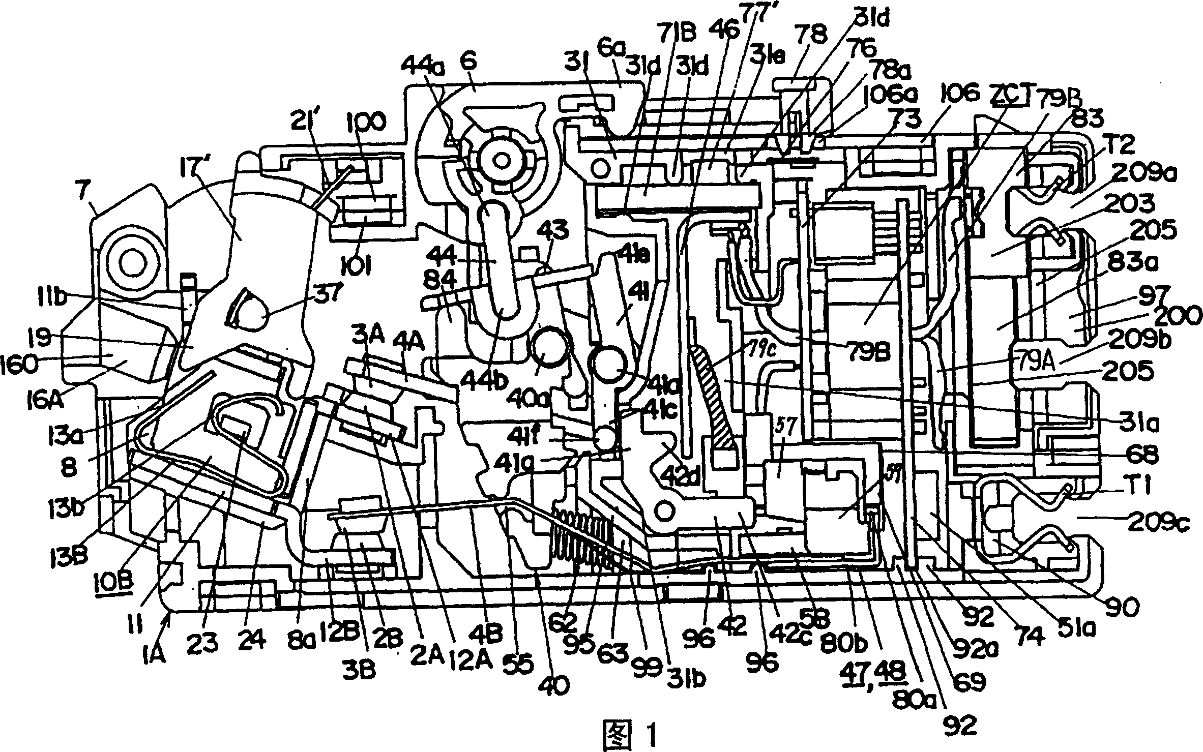
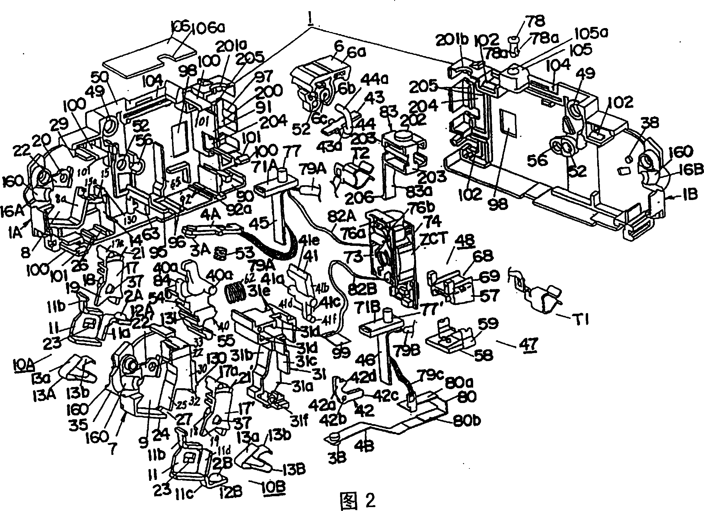
[0040]In the present embodiment, in the body 1 formed by connecting the first side case 1A and the second side case 1B made of synthetic resin on both sides, there are 2 side-by-side sides arranged in the width direction of the body 1 . Two fixed contacts 2A, 2B, and two movable contacts 4A, 4B that fix the movable contacts 3A, 3B that are freely contacted and separated from the fixed contacts 2A, 2B and oppositely arranged, and drive these two movable contacts The opening and closing mechanism 5 of the child 4A, 4B, its structure is to make each movable point 3A, 3B contact and separate with each fixed contact 2A, 2B through the opening and closing mechanism 5 through the connection and opening operation of the handle 6; Each fixed contact 2A, 2B and each movable contact 4A, 4B are arranged up and down in the height direction of the height direction. At the same ...


PUM


Abstract

The leakage breaker comprises the body containing main circuit, the handle, the first electromagnetism release device, the unit for detecting leakage current and the second electromagnetism release device. The handle from the body rotating freely can operate the switching mechanism, which turns on / off the main contact of main circuit. When over current passes through the main circuit, the first electromagnetism releases device through the release gear makes the main contact open forcibly. When leakage current is detected, the second electromagnetism release device through release gear makes the main contact open forcibly. The first electromagnetism release device possesses movable iron core and fixed iron core. The energized conductor in the main circuit is embedded in the fixed iron core. When the fixed iron core pulls the movable iron core, the release gear is released. Adding winding on the movable iron core or fixed iron core makes the second electromagnetism release device.

Description

technical field [0001] The invention relates to a leakage circuit breaker. Background technique [0002] As a conventional earth leakage circuit breaker, it is described in Unexamined-Japanese-Patent No. 11-16478. The earth leakage circuit breaker includes: the opening and closing mechanism that drives the movable contact through the rotation operation of the handle, makes the movable contact contact with the fixed contact, and separates; The composite metal sheet of the current-carrying conductor, and the fixed iron core and the movable iron core arranged in the form of sandwiching the current-carrying conductor (composite metal sheet), and when an overcurrent as large as a short-circuit current flows instantaneously in the current-carrying conductor will be able to The first electromagnetic release device that attracts the moving iron core to the fixed iron core, the zero-phase current transformer that detects the leakage current such as the ground current, and the second...

Claims


Application Information

Patent Timeline
Patent Type & Authority Patents(China)
IPC IPC(8): H01H71/24H01H73/36H01H83/14
Inventor 大井户敏宏藤雄木浩田中孝信田中毅一村省互
Owner MATSUSHITA ELECTRIC WORKS LTD
Why Eureka
Try Eureka