Method and apparatus for measuring very low fluid velocity

A flow rate, extremely low technology, applied in the field where the lower limit of measurement can reach 0.01m/s, it can solve the problems of difficult to measure differential pressure and inability to measure, and achieve the effect of easy installation and operation, low lower limit and high measurement accuracy

Inactive Publication Date: 2006-03-29
RES CENT FOR ECO ENVIRONMENTAL SCI THE CHINESE ACAD OF SCI
View PDF0 Cites 0 Cited by
  • Summary
  • Abstract
  • Description
  • Claims
  • Application Information

AI Technical Summary

Problems solved by technology

However, most of the common pressure measuring devices at present are difficult to measure small pressure differences due to the limitation of the lower limit

Method used


Image

  • Method and apparatus for measuring very low fluid velocity
  • Method and apparatus for measuring very low fluid velocity
  • Method and apparatus for measuring very low fluid velocity

Examples


Embodiment Construction

[0019] The flow velocity distribution is measured in an airlift reactor in which the fluid is water. In conjunction with the accompanying drawings, the description is as follows:

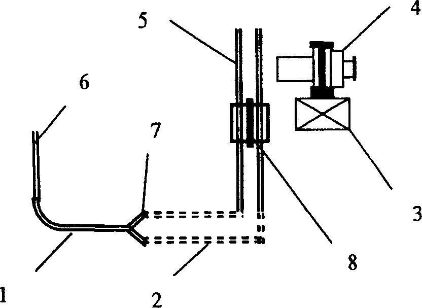
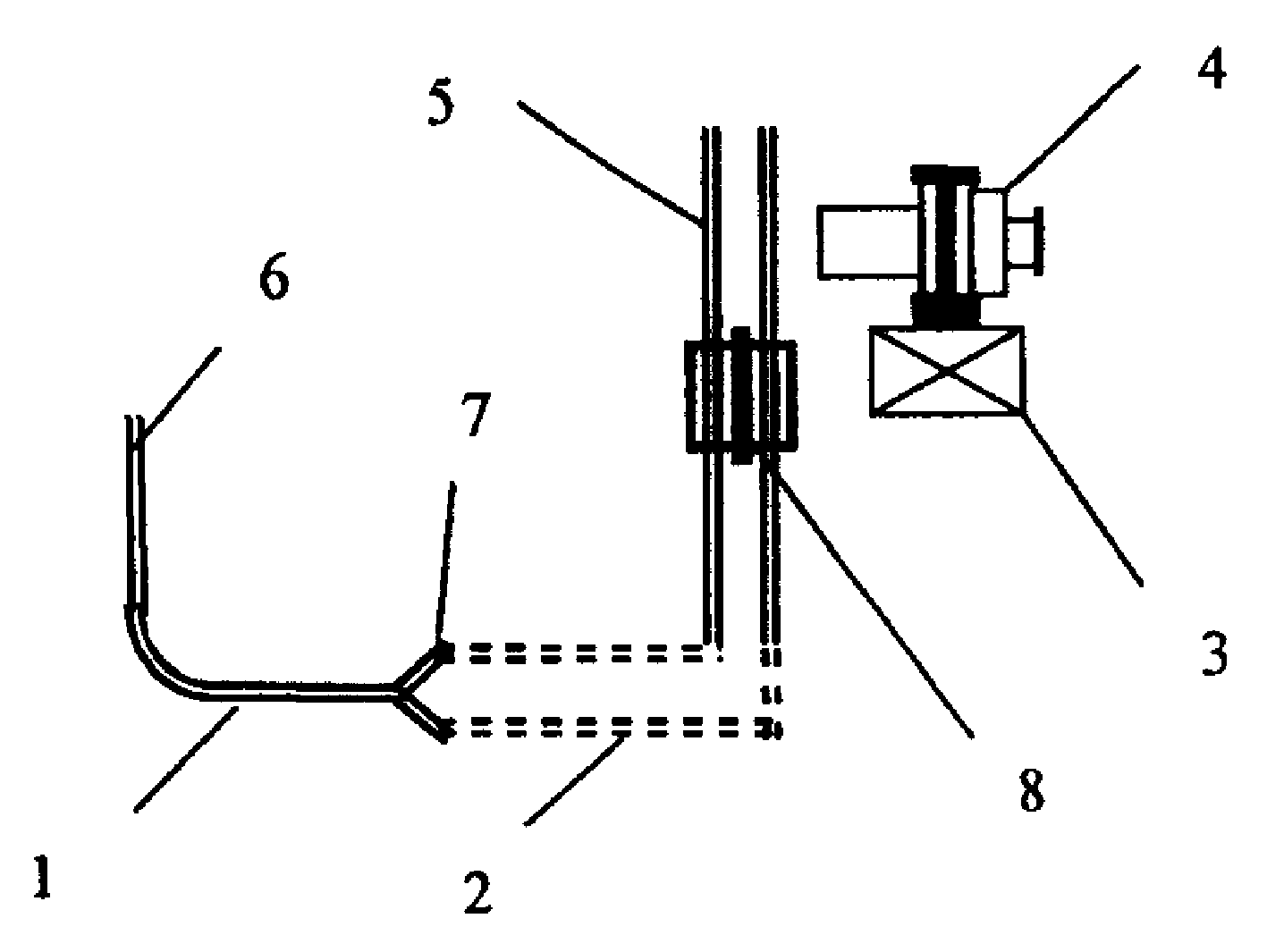
[0020] Since the medium to be measured is water with a low concentration of suspended solids, a standard pitot tube is selected as the detection device for the total head and the static head. The installation platform of the reading microscope has a universal guide rail system, which can make the reading microscope translate in three dimensions. The reading accuracy of the reading microscope is 0.0025mm. In this example, the flow velocity is less than 0.1m / s. In conjunction with the accompanying drawings, the description is as follows:

[0021] (1) Place the detection end 6 of the Pitot tube at the measuring point so that the full pressure hole of the Pitot tube is facing the streamline direction at the measuring point.

[0022] (2) Connect the pressure measuring port 7 of the Pitot tube with th...


PUM


Abstract

The invention proposes a method and device for measuring the speed of fluid inside of the container or pipe. The invention uses pitot tube as the testing device of total pressure and the static pressure, uses scale pressure testing double-tube as the testing device of pressure difference, uses the reading mricoscope as the reading device of water head in the testing tube.

Description

1. Technical field [0001] The invention discloses a method and a device for measuring fluid velocity, in particular to a method and a device with a lower measurement limit of 0.01m / s. 2. Technical Background [0002] In scientific research and engineering applications, it is sometimes necessary to measure the flow rate of a fluid (liquid or gas) at a point in a reaction vessel or pipeline. The more classical method is mainly pitot tube method. Using Pitot tube to measure speed and determine flow has strict theoretical basis, simple structure, and easy to use. It is a mature, reliable, and easy-to-use measurement method. Pitot tubes generally consist of two coaxial or parallel welded tubes. One of the tubes has a hemispherical end with a small hole at the top of the sphere, and this tube is used to display the total pressure of the fluid at the measuring point. Several small holes are opened on the wall of the other pipe, which is used to display the static pressure of the...

Claims


Application Information

Patent Timeline
IPC IPC(8): G01P5/165G01P5/17G01F1/46
Inventor 范彬栾兆坤鹿道强贾智萍
Owner RES CENT FOR ECO ENVIRONMENTAL SCI THE CHINESE ACAD OF SCI
Why Eureka
Try Eureka