

Intraocular phototropism lens and implantation method thereof
A refractive lens, lens technology, used in eye implants, intraocular lens, ophthalmic surgery, etc., can solve the problem of inability to perform any activities, no mention of intraocular refractive lenses, intraocular contact lenses only applicable, etc. question
- Summary
- Abstract
- Description
- Claims
- Application Information
AI Technical Summary
Problems solved by technology
Method used
Image

Examples
specific Embodiment 1
[0069] Other design features of the intraocular refractive lens in specific embodiment 1 are:
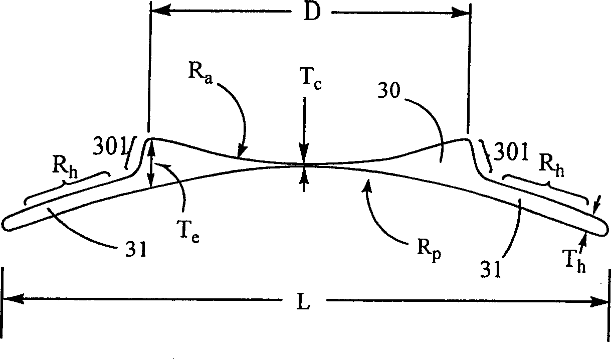
[0070] The optical body 30 is a circular structure, and its diameter D is between 4 mm and 6 mm, preferably 5 mm.
[0071] The total length L of the intraocular refractive lens 11 ranges from 10 mm to 13 mm, preferably 11 mm.
[0072] The width W of the support body 31 ranges from 4.5 mm to 6.5 mm, preferably 6 mm.
[0073] The thickness T of the support body 31 h The range is between 0.15mm and 0.3mm, preferably 0.2mm.
[0074] The radius of curvature R of the middle section of the front surface of the support body 31 h Always greater than the radius of curvature R of the rear surface of the support p , in general R h =R p +T h .
[0075] The central thickness T of the optical body 30 of the intrarefractive lens for myopia c For example, the range may be between 0.01 mm and 0.2 mm, preferably 0.1 mm.
[0076] The radius of curvature R of the front surface of the optical b...
specific Embodiment 2
[0081] Other design features of specific embodiment 2 are the same as specific embodiment 1.
[0082] The intraocular refractive lens of the present invention can correct myopia or hypermetropia in any degree. For myopia lenses, the radius of the concave surface on the front surface of the optical body determines the refractive power of the lens. Generally speaking, the lens can correct myopia from 100 degrees (-1D) to 3000 degrees (-30D). Generally, the radius of the concave surface of the front surface of the optical body can be calculated from the optical theoretical equation according to the known factors such as the refractive index and diopter of the material. In addition, the edge thickness T of the concave optical body e Generally, it should not be larger than 1mm, preferably not larger than 0.7mm. In order not to exceed this limit of edge thickness, it is necessary to reduce the diameter of the optic body to a minimum of 4.5 mm for highly myopic lenses. When makin...
specific Embodiment 4
[0088] Specific embodiment 4 such as Figure 12-14 shown. Its design is similar to that of Embodiment 3, except that its optical body is a convex and concave curved surface structure for correcting hyperopia.
[0089] According to basic principle and purpose of the present invention, the support body of the intraocular refractive lens in the specific embodiment 1-4 all can adopt such as Figure 15-17 The shape structure shown. Small holes can be set on the support body. The small hole may be circular but not limited to circular, and when circular, its diameter ranges from 0.5 mm to 2.5 mm. When it is used for the lens in the posterior chamber of the eye, on the one hand, the function of the small hole is to facilitate the operation of the doctor during the operation, and the lens can be moved to a suitable position by hooking the small hole. On the other hand, pinholes also reduce the contact surface area of the lens with the natural crystal. In addition, since the aque...
PUM
 Abstract
Description
Claims
Application Information