Corneal implant and method of manufacture

a technology of corneal implants and corneal arteries, which is applied in the field of corneal implants to achieve the effects of relieving pressure, reducing tension of bowman's membrane, and correcting the refractive error of the ey

Inactive Publication Date: 2003-09-30
REVISION OPTICS
View PDF26 Cites 70 Cited by
  • Summary
  • Abstract
  • Description
  • Claims
  • Application Information

AI Technical Summary

Benefits of technology

The present invention is directed to a corneal implant formed of a biocompatible, permeable, micro-porous hydrogel with a refractive index substantially similar to the refractive index of the cornea. The device, when placed under a lamellar dissection made in the cornea (such as a corneal flap), to relieve tension of Bowman's membrane, alters the outer surface of the cornea to correct the refractive error of the eye. By relieving the pressure and subsequent implantation of the device, the pressure points which typically are generated in present corneal surgeries are eliminated, and hence reduced risk to patients of extrusion of implants.
For astigmatic eyes, implants are fabricated with a cylindrical addition along one of the axes. This device can be oval or elliptical in shape, with a longer axis either in the direction of cylindrical power addition or perpendicular to it. The implant preferably has a pair of markers such as, for example, protrusions, indentations or other types of visual indicators, in the direction of the cylindrical axis to easily mark and identify this direction. This indexing assists the surgeon in the proper placement of the implant under the flap with the correct orientation during surgery to correct astigmatism in any axis.
The material from which any one or more of these implants are made is preferably a clear, permeably, microporous hydrogel with a water content greater than 40% up to approximately 90%. The refractive index should be substantially identical to the refractive index of corneal tissue. The permeability of the material is effected through a network of irregular passageways such as to permit adequate nutrient and fluid transfer to prevent tissue necrosis, but which are small enough to act as a barrier against the tissue ingrowth from one side of the implant to another. This helps the transmembrane tissue viability while continuing to make the implant removable and exchangeable.
The refractive index of the implant material should be in the range of 1.36-1.39, which is substantially similar to that of the cornea (1.376). This substantially similar refractive index prevents optical aberrations due to edge effects at the cornea-implant interface.

Problems solved by technology

Extrusion is undesirable because it tends to cause clinical complications and product failure.

Method used


Image

  • Corneal implant and method of manufacture
  • Corneal implant and method of manufacture
  • Corneal implant and method of manufacture

Examples


Embodiment Construction

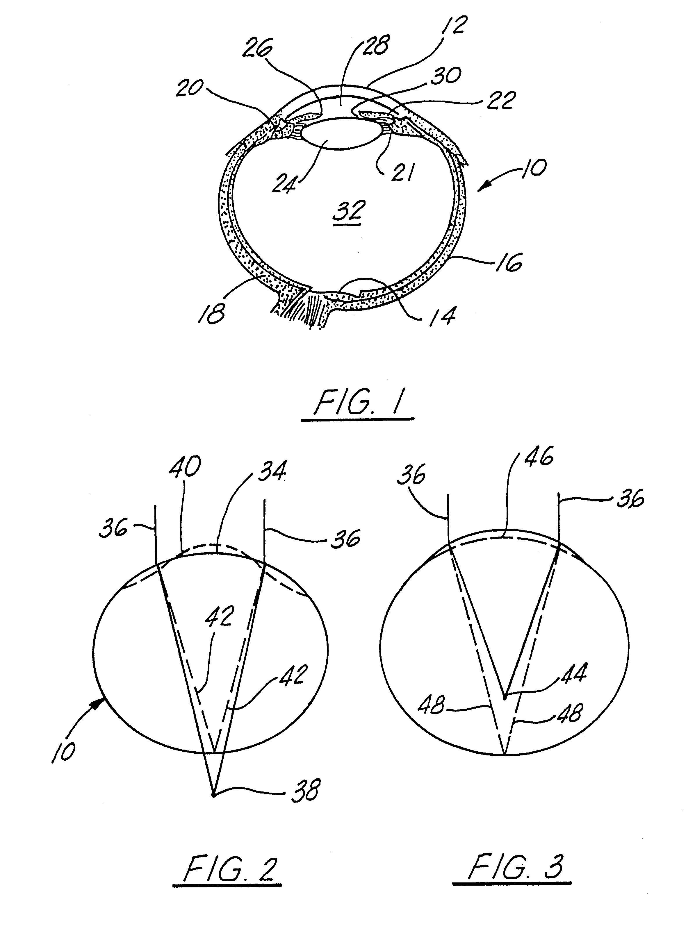
Referring first to FIG. 1 of the drawings, a schematic representation of the globe of the eye 10 is shown, which resembles a sphere with an anterior bulged spherical portion 12 that represents the cornea. The eye 10 is made up of three concentric coverings that enclose the various transparent media through which light must pass before reaching the light sensitive retina 14.

The outer-most covering is a fibrous protective portion that includes a posterior layer which is white and opaque, called the sclera 16, which is sometimes referred to as the white of the eye where it is visible from the front. The anterior 1 / 6th of this outer layer is the transparent cornea 12.

A middle covering is mainly vascular and nutritive in function and is made up of the choroid 18, the ciliary 20 and the iris 22. The choroid generally functions to maintain the retina. The ciliary muscle 21 is involved in suspending the lens 24 and accommodating the lens. The iris 22 is the most anterior portion of the midd...


PUM


Abstract

Prosthetic implants designed to be implanted in the cornea for modifying the cornea curvature and altering the corneal refractive power for correcting myopia, and myopia with astigmatism, such implants formed of a micro-porous hydrogel material.

Description

The field of this invention relates to prosthetic implants designed to be implanted in the cornea for modifying the cornea curvature and altering the corneal refractive power for correcting myopia, hyperopia, astigmatism, and presbyopia, and, in addition, to such implants formed of a micro-porous hydrogel material.It is well known that anomalies in the shape of the eye can be the cause of visual disorders. Normal vision occurs when light that passes through and is refracted by the cornea, the lens, and other portions of the eye, and converges at or near the retina. Myopia or nearsightedness occurs when the light converges at a point before it reaches the retina and, conversely, hyperopia or farsightedness occurs when the light converges a point beyond the retina. Other abnormal conditions include astigmatism where the outer surface of the cornea is irregular in shape and effects the ability of light to be refracted by the cornea. In addition, in patients who are older, a condition c...

Claims


Application Information

Patent Timeline
Patent Type & Authority Patents(United States)
IPC IPC(8): A61F2/14
CPCA61F2/147
Inventor NIGAM, ALOK
Owner REVISION OPTICS
Why Eureka
Try Eureka