Distributed security emergency system and method for controlling its components

A distributed and safe technology, applied in distributed safety emergency systems, to control the components of the X-by-Wire system in the vehicle, in the field of computer programs

Inactive Publication Date: 2006-04-26
ROBERT BOSCH GMBH
View PDF1 Cites 0 Cited by
  • Summary
  • Abstract
  • Description
  • Claims
  • Application Information

AI Technical Summary

Problems solved by technology

[0018] A disadvantage of the prior art is that the logic level L4 is always realized in a separate component, which - for example in the wheel module of the electric brake system - must also be set up repeatedly in the distribution type safety emergency system

Method used


Image

  • Distributed security emergency system and method for controlling its components
  • Distributed security emergency system and method for controlling its components
  • Distributed security emergency system and method for controlling its components

Examples


Embodiment Construction

[0038] The method according to the invention will be described below with the aid of an electric braking system. However, the invention is not restricted to electrical braking systems, but can be applied to any distributed safety emergency system. The invention makes it possible to reliably release components of the safety emergency system without using additional monitoring units. Specifically, the task of the monitoring unit is taken over by a unit of the safety emergency system which is also provided in the system anyway.

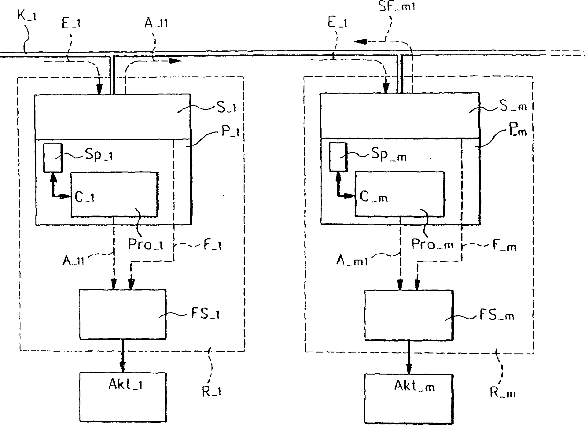
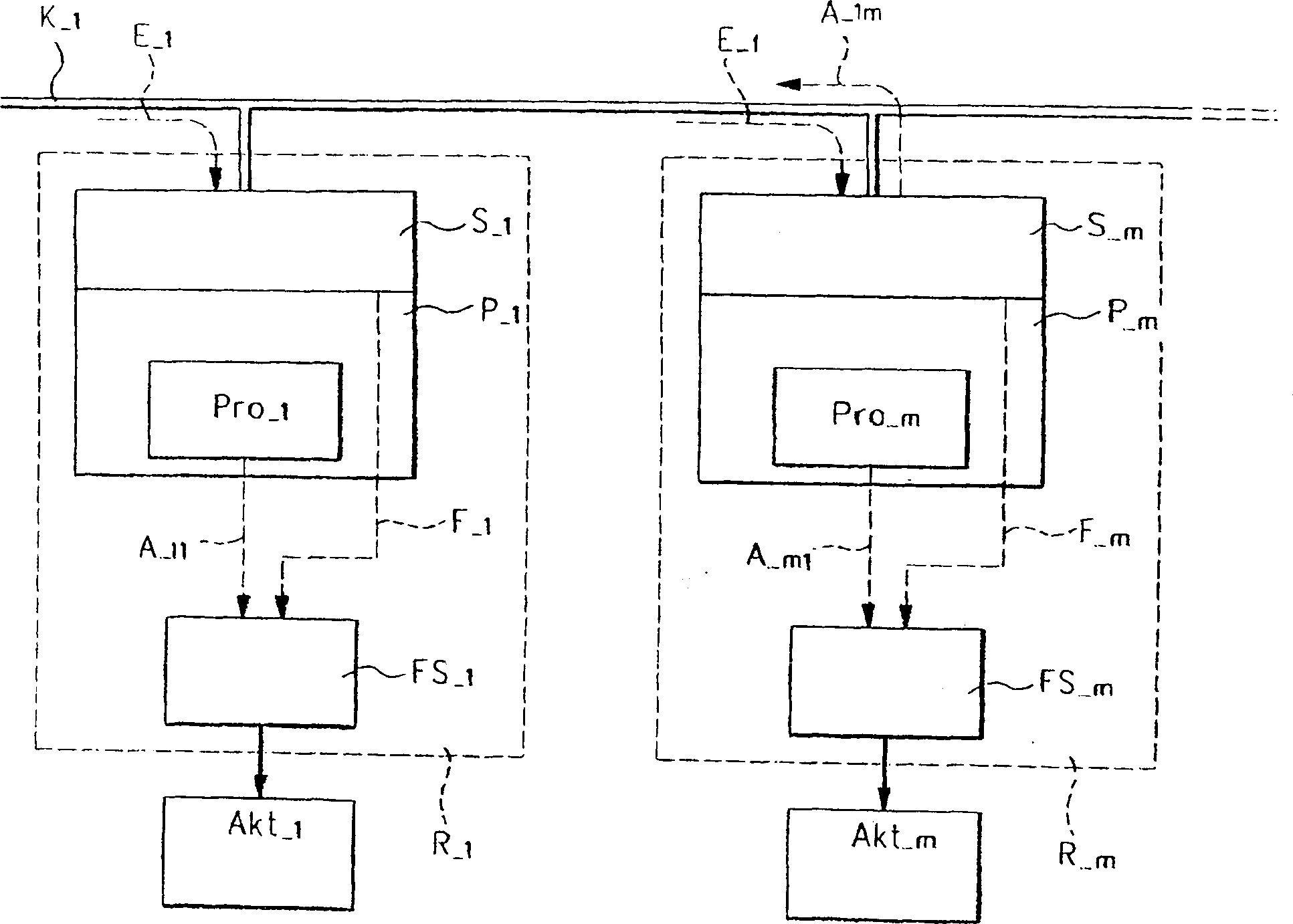
[0039] The brake system includes a wheel module R_1, R_m for each wheel to be braked. Each wheel module R_1 , R_m includes a microcomputer system P_1 , P_m and a release circuit FS_1 , FS_m. The microcomputer systems P_1, P_m respectively include a microprocessor Pro_1, Pro_m and an intelligent communication controller S_1, S_m. The microprocessors Pro_1 , Pro_m and the communication controllers S_1 , S_m of the microcomputer systems P_1 , P_m can be ...


PUM


Abstract

The invention relates to a method for controlling a component (Akt_1) of a distributed emergency safety system, in particular a component (Akt_1) of an X-by-Wire system in a vehicle. The component (Akt_1) is controlled by a first control module (R_1) assigned to the component (Akt_1) using at least one first microcomputer system (P_1). A monitoring unit independent of the first microcomputer system (P_1) is provided for monitoring the microcomputer system (P_1). The invention proposes that the safety emergency system has at least one other microcomputer system (P_m) in addition to the first microcomputer system (P_1), which for data transmission purposes, for example Maintain communication with said first microcomputer system (P_1) via a physical data bus (K_1). In this case, the task of the monitoring unit is taken over by the other microcomputer system (P_m). A separate monitoring unit can thus be dispensed with.

Description

technical field [0001] The invention relates to a method for controlling components of a distributed safety emergency system, in particular of an X-by-Wire system (safety-related failsafe system in a vehicle) in a vehicle. The components are controlled by a first control module assigned to the components using at least one first microcomputer system. The invention also relates accordingly to such a distributed security emergency system. [0002] The control of components includes the following steps: [0003] a) obtaining at least one control signal for said component according to at least one input signal by said first microcomputer system; [0004] b) determining at least one logic control signal, wherein said at least one logic control signal is determined at least partially by a monitoring unit independent of said first microcomputer system from said at least one input signal; [0005] c) comparing said at least one control signal with said at least one logic control si...

Claims


Application Information

Patent Timeline
Patent Type & Authority Patents(China)
IPC IPC(8): B60T8/88B60T17/22B60T13/74G05B19/042G05B19/048H01L27/115G11C16/02B60T7/04B60T8/17B60T8/96B60W50/00B60W50/02B60W50/04G05B9/03G06F11/00G06F11/16G06F11/18
CPCB60G2600/042B60G2600/08B60G2800/80B60T7/042B60T8/885B60T13/74B60T13/741B60T2270/404B60T2270/82B60W2050/0005B60W2050/0045B60W2050/021B60W2050/0292B60W2050/041G05B9/03G06F11/1637G06F11/18G06F11/182
Inventor H·赫克曼恩R·维伯勒B·科斯奇P·布勒斯辛格
Owner ROBERT BOSCH GMBH
Why Eureka
Try Eureka