
Integrated material feeder of sheet adhesive machine

A feeder and integrated technology, which is applied in the direction of electrical components, electrical components, and electrical components to assemble printed circuits, etc., can solve the problem of feeding accuracy that is difficult to meet high-speed, high-precision feeding, inaccurate material position compensation or correction, and feeding Unreasonable device structure and other problems, to achieve the effect of enriching control modes, improving precision, and increasing placement speed

Inactive Publication Date: 2006-05-24
广州市羊城科技实业有限公司
View PDF0 Cites 0 Cited by
  • Summary
  • Abstract
  • Description
  • Claims
  • Application Information

AI Technical Summary

Problems solved by technology

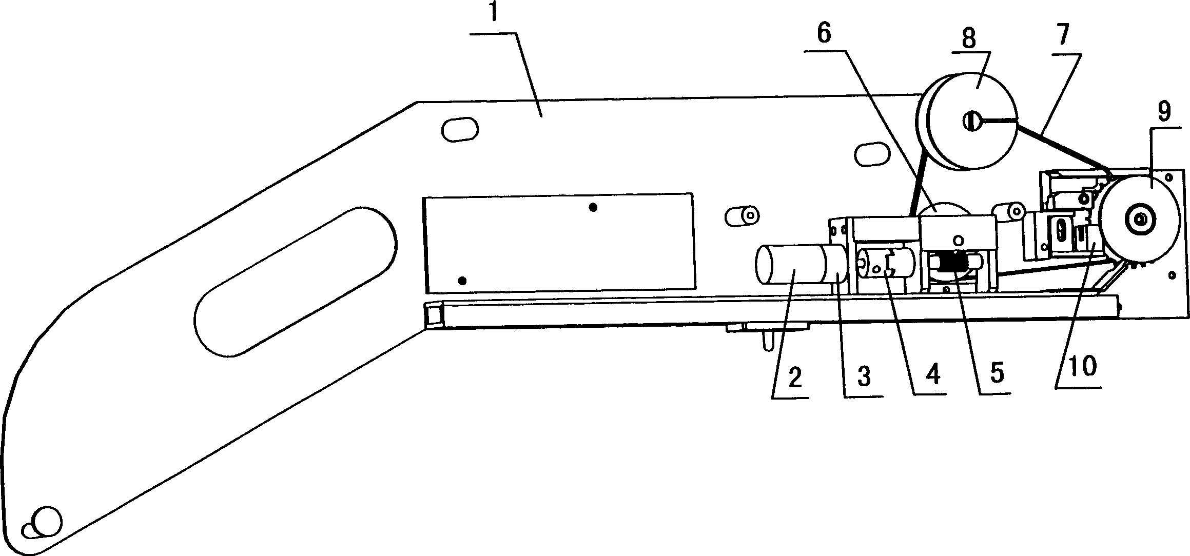
[0003] In the existing technology at home and abroad, considering that the placement machine has various advanced digital electronic control equipment or visual compensators, it can compensate or correct the inaccurate position of the material, so the structure of the feeder Little attention has been paid to the improvement, so that the structure of the feeder is unreasonable: it includes a DC motor, which changes the speed through a transmission and then transmits the power to the synchronous belt drive wheel through mechanical transmission mechanisms such as couplings and worm gears. Then drive the peeling wheel synchronously through the synchronous belt to peel off the protective film covered on the surface of the parts belt, and at the same time drive the feeding gear to feed forward, and use the photoelectric counters installed on both sides of the feeding gear to perform material counting and speed control.
Since there are as many as 3 to 4 mechanical transmission links in the feeder assembly of the prior art, and the synchronization accuracy of the synchronous belt is also very low, the accumulation of transmission errors step by step is very large, and it is also difficult to reduce these accumulated errors. Therefore, the feeding accuracy of the existing feeder is difficult to meet the requirements of high-speed and high-precision feeding, which will inevitably limit the further replacement and technical upgrading of the existing placement machine, and drag the technological progress of the placement machine.

Method used


Image

  • Integrated material feeder of sheet adhesive machine
  • Integrated material feeder of sheet adhesive machine
  • Integrated material feeder of sheet adhesive machine

Examples


Embodiment Construction

[0022] Embodiments of the present invention,

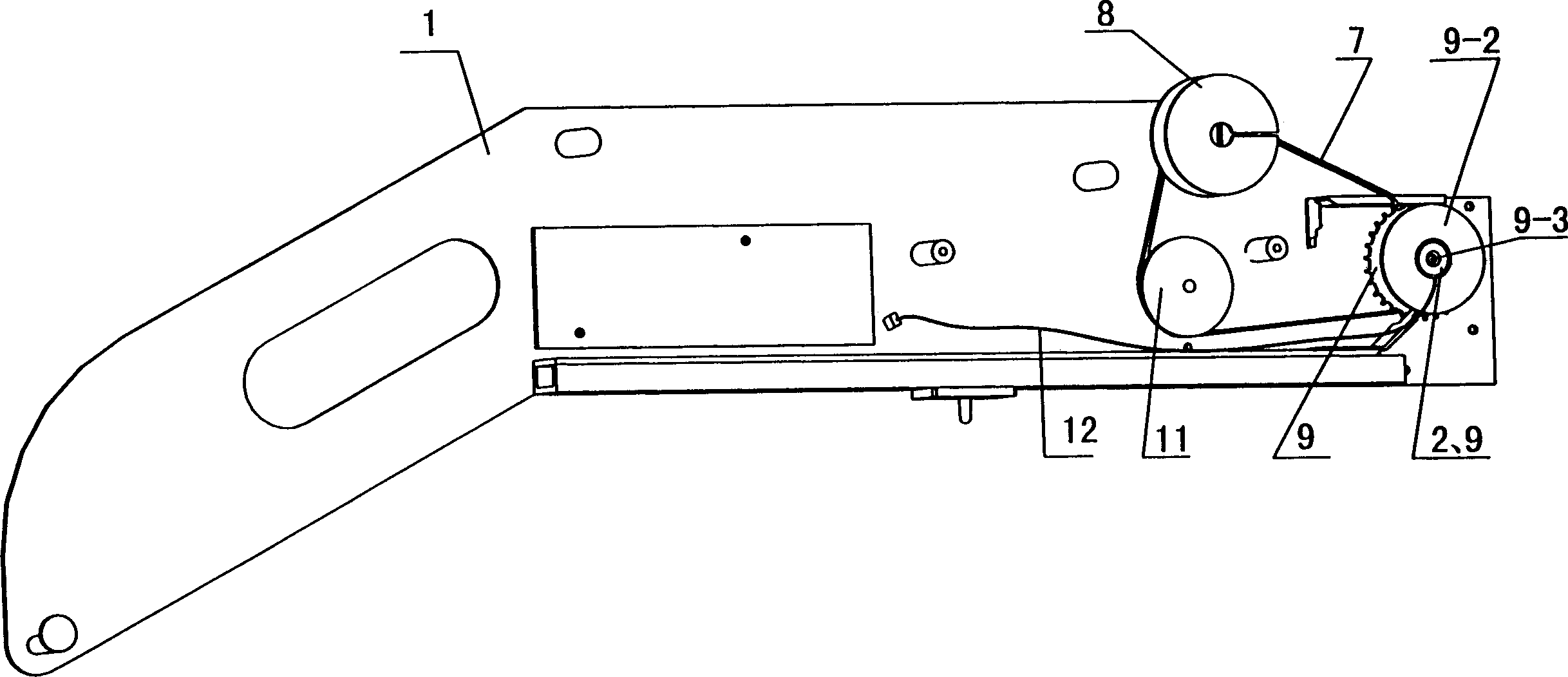
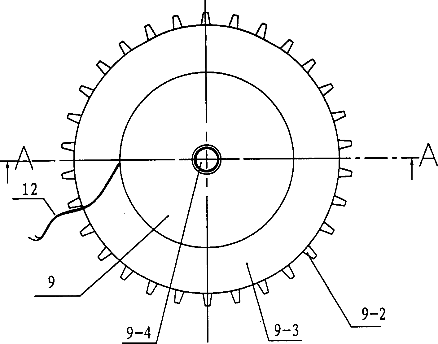
[0023] Such as figure 2 , 3 , Shown in 4 and 5: the integrated feeder of the placement machine of the present invention has the following parts on the support plate 1 of the integrated feeder: the active feed wheel integrated with the drive motor linked with the synchronous belt 7 9. Peeling wheel 8, in the active feeding wheel 9 integrated with the drive motor, the synchronous transmission gear 9-1, the feeding gear 9-2 and the annular supporting wheel 9-3 with the same rotation center are connected to form a column wheel cavity 9-0, and a stator coil 2-0 is installed in its cylindrical wheel cavity 9-0, and a rotor coil 2-1 is installed on its original wheel shaft 9-4; the wheel cavity 9 -0 cooperates with the wheel shaft 9-3 by two rolling bearings 9-5 in the axial direction.

[0024] The axle 9-4 of the active feeding wheel 9 is fixed on the support plate 1 of the integrated feeder;

[0025] The synchronous transmission g...


PUM


Abstract

The invention discloses an integrated feeder of a placement machine, which includes a drive system, a peeling wheel, and a feed wheel, and is characterized in that: the drive motor in the drive system is integrated with the feed wheel , forming an active feeding wheel. In the active feeding wheel, the synchronous transmission gear with the same rotation center, the feeding gear and the annular supporting wheel are integrated and a stator magnet or coil is installed in its cylindrical wheel cavity, correspondingly on its original wheel shaft The rotor coil or magnet is installed on the top; the wheel cavity and the wheel shaft are matched by two rolling bearings in the axial direction. The axle of the active feeding wheel is fixed on the support plate of the integrated feeder; the synchronous transmission gear drives the skinning wheel to rotate in the same direction or in the opposite direction through a synchronous belt. The invention has reasonable structural layout, greatly reduced mechanical transmission links, small assembly volume and light weight, and can significantly improve the responsiveness and accuracy of the feeding action.

Description

【Technical field】 [0001] The invention relates to the field of placement machines for electronic assembly, in particular to the technical field of a placement machine for electronic assembly and a feeder assembly thereof. 【Background technique】 [0002] Now, electronic information products, mechanical and electrical products, household appliances, etc. are inseparable from printed circuit boards and integrated circuit chips, and electronic components such as resistance, capacitance, Inductive components, integrated circuit chips, logic circuits, etc. constitute practical functional electronic devices, and the size of the above-mentioned spare parts is getting smaller and smaller. Before leaving the factory, these spare parts with an area between rice grains or even smaller than sesame seeds are all processed Stored on very long strips of paper and plastic parts at precise intervals, covered with a protective film, and then rolled into a disk for easy packaging, transportatio...

Claims


Application Information

Patent Timeline
Patent Type & Authority Patents(China)
IPC IPC(8): H05K13/02H05K3/30
Inventor 宋福民张小丽陈真李萍
Owner 广州市羊城科技实业有限公司
Learn More