Mounting head unit for electronic components

A technology for electronic components and working heads, which is applied in the direction of electrical components, electrical components, and assembling printed circuits with electrical components, can solve the problem of increasing the volume and weight of the mounting work head, increasing the control structure and control cost, and inconvenient to use and operate. And maintenance and other issues, to achieve the effect of compact structure, simple structure, weight reduction

Active Publication Date: 2017-01-04
SHANDONG RIFA TEXTILE MACHINERY
View PDF3 Cites 0 Cited by
  • Summary
  • Abstract
  • Description
  • Claims
  • Application Information

AI Technical Summary

Problems solved by technology

In order to increase production capacity, it is necessary to arrange multiple placement work head units adjacent to each other. The disadvantage of this arrangement is that the overall volume of the placement equipment is large and occupies a large area; secondly, multiple adjacently arranged The placement working head unit is beyond the range of one camera, and multiple camera recognition units need to be configured, which increases the control structure and control cost
In addition, some electronic component surface mount devices use a placement head unit that can pick up and place simultaneously from a component supply device, and can recognize all components with a single component recognition camera. However, when using this type of work head unit, To achieve an increase in production capacity, it is necessary to increase the number of nozzle pivots, but the problem with the increase in the number of nozzle pivots is that the volume and weight of the placement work head are increased, and the mechanism is more complicated and prone to failure. Ease of use, operation and maintenance

Method used


Image

  • Mounting head unit for electronic components
  • Mounting head unit for electronic components
  • Mounting head unit for electronic components

Examples


Embodiment Construction

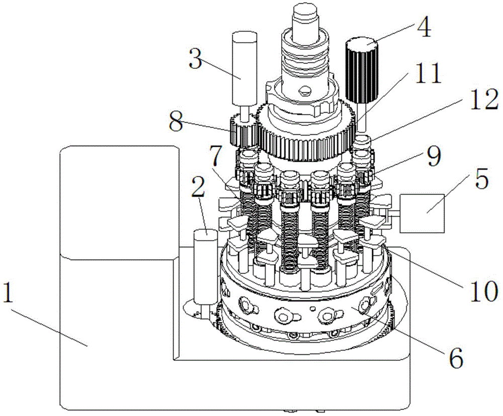
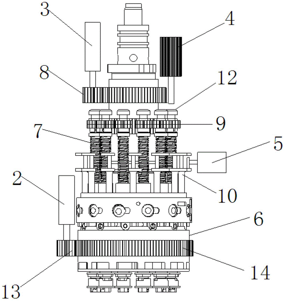
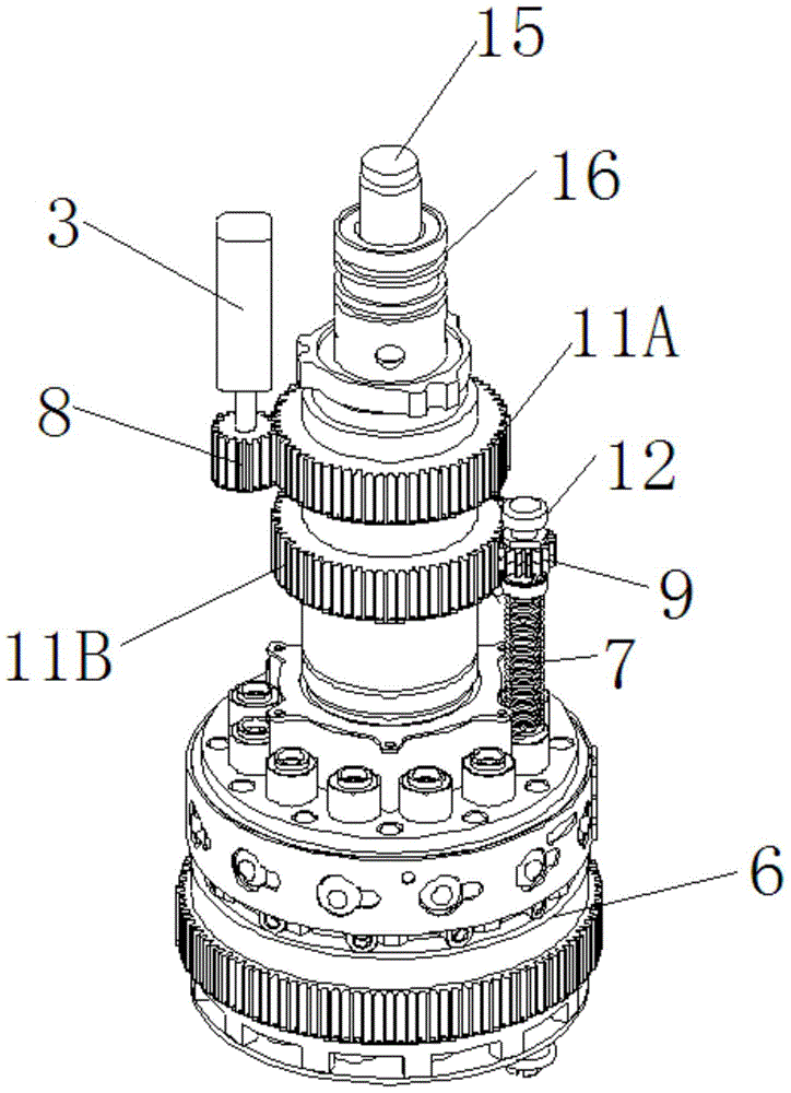
[0031] In order to better understand the present invention, the implementation manner of the present invention will be explained in detail below in conjunction with the accompanying drawings.

[0032] A placement work head unit for electronic components, such as figure 1 As shown, it is a placement working head unit that can rotate in a horizontal plane and can pick up and place multiple electronic components, including a working head body 1, a transmission mechanism in the R-axis direction, a transmission mechanism in the θ-axis direction, The transmission mechanism in the Z-axis direction, the positive pressure air source and the negative pressure air source and the control mechanism, the transmission mechanism in the R-axis direction is connected with the working head body 1, and the transmission mechanism in the θ-axis direction is respectively connected with the transmission mechanism in the R-axis direction , and the working head body 1, and the transmission mechanism in...


PUM


Abstract

The invention discloses a surface-mounted work head unit of an electronic component. The surface-mounted work head unit comprises a work head body, a transmission mechanism in the R-axis direction, a transmission mechanism in the theta-axis direction, a transmission mechanism in the Z-axis direction, a positive pressure air source, a negative pressure air source and a control mechanism. The transmission mechanism in the R-axis direction is connected with the work head body, the transmission mechanism in the theta-axis direction is respectively connected with the transmission mechanism in the R-axis direction and the work head body, and the transmission mechanism in the Z-axis direction is respectively connected with the work head body, the transmission mechanism in the R-axis direction and the transmission mechanism in the theta-axis direction. The surface-mounted work head unit is simple and compact in structure, light, high in surface mounting speed, low in inertia and high in reliability, and prolongs the service life of equipment.

Description

technical field [0001] The invention relates to a mounting working head in the field of electronic mounting, in particular to a mounting working head unit of electronic components capable of rotating in a horizontal plane and capable of picking up and mounting multiple components. Background technique [0002] In the field of surface mount technology (SMT), prior art surface mount devices for electronic components, such as placement work head units, pick up components from the component supply and place the components on the printed circuit with the aid of a vision system On the specific position of the board (PCB), the placement work is completed. In order to increase production capacity, it is necessary to arrange multiple placement work head units adjacent to each other. The disadvantage of this arrangement is that the overall volume of the placement equipment is large and occupies a large area; secondly, multiple adjacently arranged The placement working head unit is be...

Claims


Application Information

Patent Timeline
Patent Type & Authority Patents(China)
IPC IPC(8): H05K3/30H05K13/02H05K13/04
Inventor 李子军孙宇丁士新祁玉斌
Owner SHANDONG RIFA TEXTILE MACHINERY
Why Eureka
Try Eureka