
Anti-shock device

A technology of anti-seismic devices and components, applied in the direction of anti-seismic, building components, building structures, etc., to achieve the effects of increasing torsional stiffness, reducing directionality, and preventing resistance

Inactive Publication Date: 2006-06-14
NIPPON STEEL & SUMIKIN ENG CO LTD
View PDF3 Cites 0 Cited by
  • Summary
  • Abstract
  • Description
  • Claims
  • Application Information

AI Technical Summary

Problems solved by technology

[0006] In addition, also in JP Unexamined Patent Publication No. 60-223576 (Patent Document 4), a U-shaped anti-seismic device is described, but this document does not address the performance of the anti-seismic device when horizontal deformation occurs in any direction of the earthquake. directional description

Method used


Image

  • Anti-shock device
  • Anti-shock device
  • Anti-shock device

Examples


no. 1 Embodiment

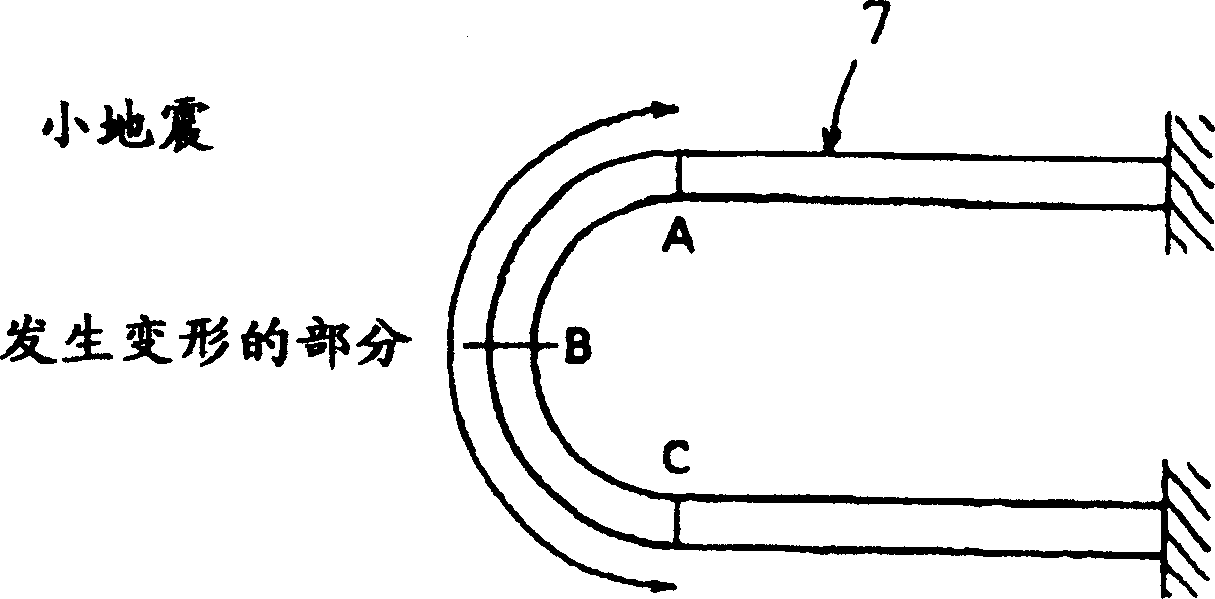
[0129] Fig. 6 shows an embodiment of the present invention. In this embodiment, an attenuation mechanism 6 is provided between the upper structure 2 and the bottom structure 3 interposed with the isolator 1 . The attenuation mechanism 6 adopts a plurality of curved parts 7 formed from elastic-plastic materials into a substantially U-shape as shown in FIG. In this way, two curved members are combined to form a set, and a plurality of sets of such sets are used. As shown in FIG. 9, the curved member 7 is, for example, made of elastoplastic material, and a steel material with a rectangular cross-section of 25 mm in length and 50 mm in width is formed into a curved shape. After forming, if necessary, heat treatment is performed to remove residual deformation. The installation part 8 at one end of the corresponding curved part 7 is fixed on the upper structure 2 , and the installation part 9 at the other end is fixed on the bottom structure 3 .

[0130] In addition, when the atte...

no. 2 Embodiment

[0147] Fig. 18 shows an embodiment of the present invention. This embodiment is the following anti-seismic device, wherein, on the outer periphery of the isolator 1 sandwiched between the upper structure 2 and the bottom structure 3, a curved member 7 constituting the damping mechanism 6 is provided, and the isolator 1 and the curved member 7 set integrally. As shown in Figure 19, on the outer periphery of the connecting plate 14 connecting the isolator 1, the isolator with the upper structure 2 and the bottom structure 3, two or more of them are curved and are formed of elastic-plastic materials. Components 7 are circular as shown in Figure 20 and Figure 21, arranged at equiangular intervals, and combined in a lantern shape, or as shown in Figure 22 and Figure 23, two curved components 7 are line-symmetric Combined in different ways, thus forming a group, and the multiple groups of components are arranged on the outer periphery of the isolator 1 . In the process of installi...


PUM


Abstract

A plastic hysteresis type anti-seismic device, the anti-seismic device has an isolator (1) formed by alternately stacking metal plates and elastic bodies, and a plurality of curved parts ( 7), the two ends (8, 9) of the curved part are respectively fixed on the upper structure (2) and the bottom structure (3), except the two ends (8, 9) of the above-mentioned curved part (7) The rest of the middle part is arranged in a manner separated from the upper structure (2) and the bottom structure (3).

Description

technical field [0001] The present invention relates to a plastic hysteresis type anti-seismic device installed between a superstructure and a bottom structure to attenuate the vibration of the superstructure during an earthquake and absorb earthquake energy. Background technique [0002] In the past, various types of anti-seismic devices have been proposed by changing the shape of the parts as plastic hysteresis type anti-seismic devices installed between the building structure and the superstructure and substructure such as the foundation supporting the structure. [0003] For example, JP Patent Publication No. 2-62671 (Patent Document 1) discloses a device in which an anti-seismic device is formed in a straight rod shape and each end is fixed to an upper and lower structure. In addition, JP Patent Publication No. 2-59262 (Patent Document 2) discloses an anti-vibration device formed into a ring shape. [0004] For example, JP-A-2-194233 (Patent Document 3) discloses a dev...

Claims


Application Information

Patent Timeline
Patent Type & Authority Patents(China)
IPC IPC(8): E04B1/98E04B1/36E04H9/02F16F15/02F16F15/04
Inventor 佐伯英一郎渡边厚铃木一弁
Owner NIPPON STEEL & SUMIKIN ENG CO LTD
Learn More