Supercharge Your Innovation With Domain-Expert AI Agents!

Ultrasonic cleaning apparatus and ultrasonic claning method

A cleaning device and ultrasonic technology, applied in cleaning methods and appliances, cleaning methods using liquids, chemical instruments and methods, etc., can solve problems such as large loss of ultrasonic waves, difficulty in ultrasonic cleaning, and large loss of cleaning liquid

Inactive Publication Date: 2006-06-28
ALPS ALPINE CO LTD
View PDF1 Cites 0 Cited by
  • Summary
  • Abstract
  • Description
  • Claims
  • Application Information

AI Technical Summary

Problems solved by technology

Therefore, the ultrasonic wave generated by the outer tank has been attenuated when it is transmitted into the cleaning cylinder, and it is difficult to use the generated ultrasonic wave to clean effectively, and the loss of the ultrasonic wave is also large.
In addition, in order to transmit the ultrasonic wave to the cleaning liquid in the cleaning cylinder, in addition to the cleaning liquid in the cleaning cylinder used for cleaning, the outer tank containing the cleaning cylinder must also be filled with cleaning liquid, and the loss of cleaning liquid is large, resulting in Obstacles to miniaturization of cleaning devices

Method used


Image

  • Ultrasonic cleaning apparatus and ultrasonic claning method
  • Ultrasonic cleaning apparatus and ultrasonic claning method
  • Ultrasonic cleaning apparatus and ultrasonic claning method

Examples


Embodiment Construction

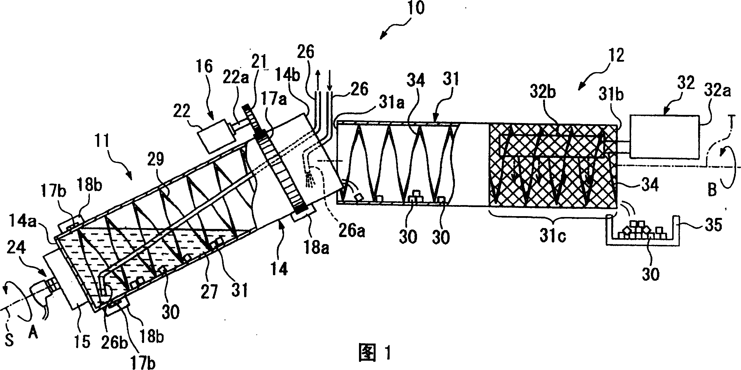
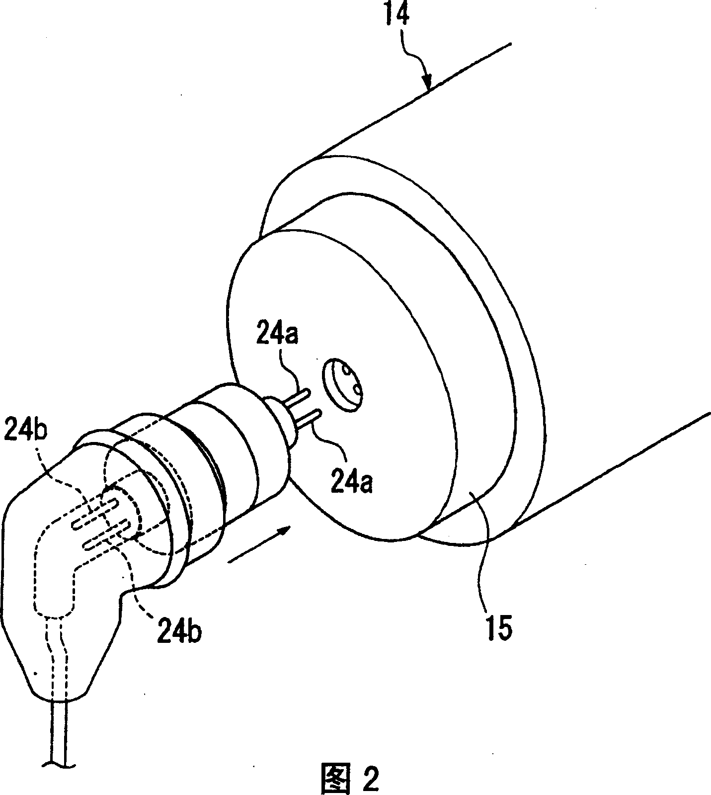
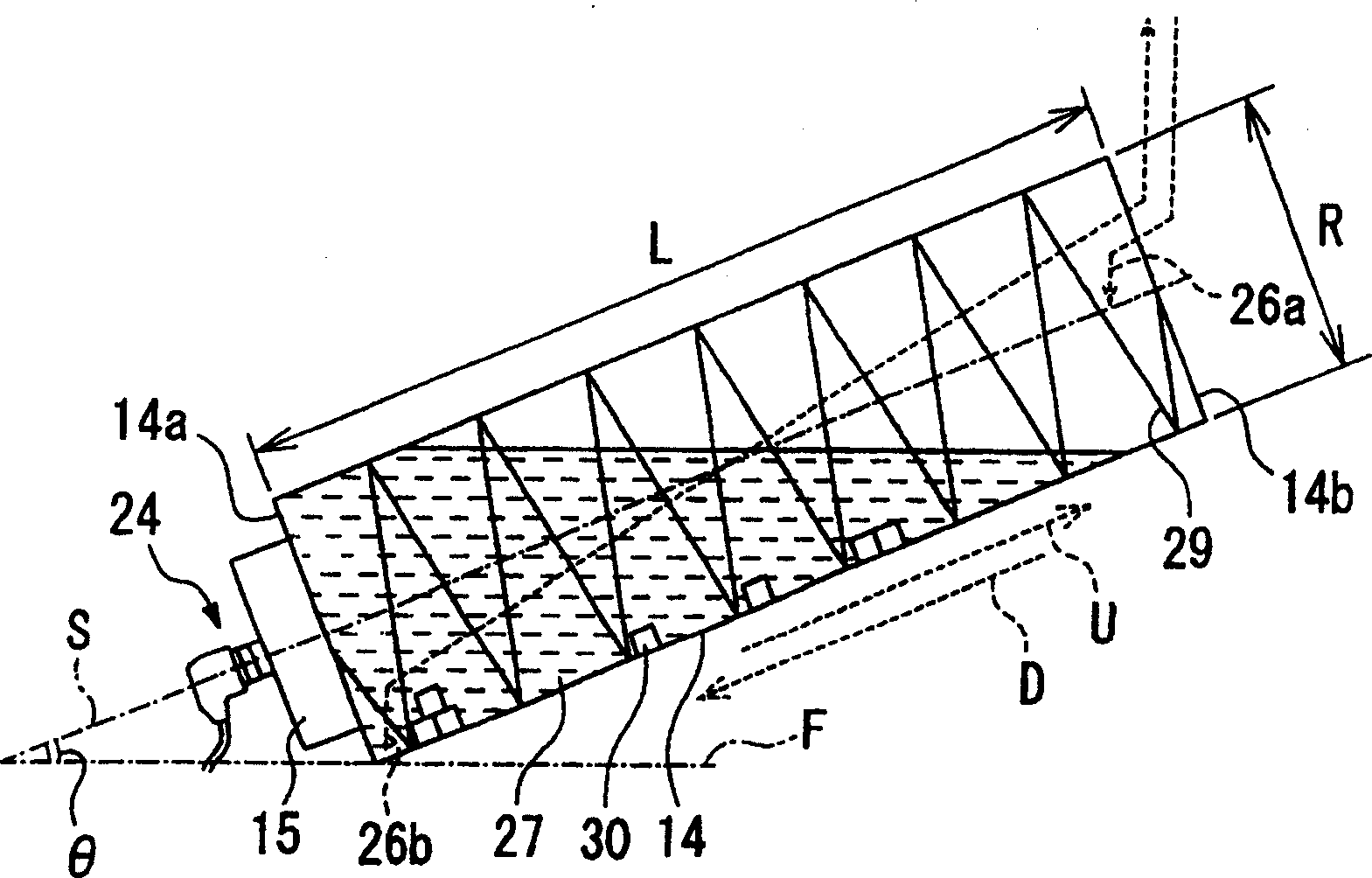
[0022] Embodiments of the present invention will be described below with reference to the accompanying drawings. Fig. 1 is a sectional view showing a part of an ultrasonic cleaning device according to the present invention. The ultrasonic cleaning device 10 has a cleaning unit 11 and a drying unit (drying device) 12 . The cleaning unit 11 is composed of a cleaning cylinder 14 , an ultrasonic vibration unit (ultrasonic wave generation mechanism) 15 and a rotation mechanism (rotation device) 16 . The cleaning cylinder 14 is a substantially cylindrical cleaning tank with one end (bottom surface side) 14a having a closed side and the other end 14b being open, inclined relative to the horizontal plane, and is made of, for example, stainless steel.

[0023] Racks 17a, 17b are provided around the outer circumferential surface on both sides of the lengthwise direction of the cleaning cylinder 14. On the outside of the cleaning cylinder 14, there is formed a rack that is slidably conn...


PUM


Abstract

Provided is an ultrasonic cleaning apparatus capable of efficiently utilizing ultrasound, cleaning with a small amount of a cleaning liquid, and contributing to downsizing of the apparatus. The ultrasonic cleaning apparatus 10 can provide an ultrasonic wave with almost no attenuation to the cleaning liquid 27 and can strongly provide an ultrasonic vibration to the cleaning liquid 27 by an ultrasonic vibration unit 15 which is directly mounted on a cleaning drum 14 and is rotated together therewith. For the ultrasonic vibration unit 15, it is unnecessary to use a large output in consideration of attenuation, and the cleaning liquid 27 can be vibrated efficiently and with a small amount of electric power consumption by ultrasonic vibration. In addition, as the ultrasonic vibration unit 15 is directly mounted on the cleaning drum 14, it is unnecessary to use a liquid and an outer tank for transmitting the ultrasonic vibration to the surrounding of the cleaning drum 14, and it is therefore possible to remarkably perform size reduction and weight reduction of the ultrasonic cleaning apparatus 10.

Description

technical field [0001] The invention relates to an ultrasonic cleaning device, in particular to an ultrasonic cleaning device using a rotary cleaning cylinder. Background technique [0002] Ultrasonic cleaning devices that use an ultrasonic vibrator or the like to generate ultrasonic vibrations in a cleaning liquid such as water to remove dirt adhering to the object to be cleaned are widely used. Such an ultrasonic cleaning device generally installs an ultrasonic vibrator on the bottom surface of a cleaning tank storing a cleaning liquid to ultrasonically vibrate the cleaning liquid. [0003] On the other hand, in order to improve the cleaning ability of such an ultrasonic cleaning device and realize high-efficiency cleaning, an ultrasonic cleaning device equipped with an ultrasonic generating mechanism such as an ultrasonic vibrator on a cleaning device called a spiral cleaner is widely known. (For example, refer to Patent Document 1) [0004] 【Patent Document 1】 [0005...

Claims


Application Information

Patent Timeline
Patent Type & Authority Patents(China)
IPC IPC(8): B08B3/12B06B1/06B08B3/04
Inventor 芳贺宣明三森健一
Owner ALPS ALPINE CO LTD
Features
  • R&D
  • Intellectual Property
  • Life Sciences
  • Materials
  • Tech Scout
  • Unparalleled Data Quality
  • Higher Quality Content
  • 60% Fewer Hallucinations
Learn More