

Golf head with its joint part forms a slug hole
A technology for golf club heads and joints, applied to golf balls, golf clubs, rackets, etc., which can solve the negative effects of increasing the risk of 1” fracture or distortion of the golf club head, and cannot substantially improve the hitting performance. Increase the moment of inertia, etc.
- Summary
- Abstract
- Description
- Claims
- Application Information
AI Technical Summary
Problems solved by technology
Method used
Image

Examples
Embodiment 1
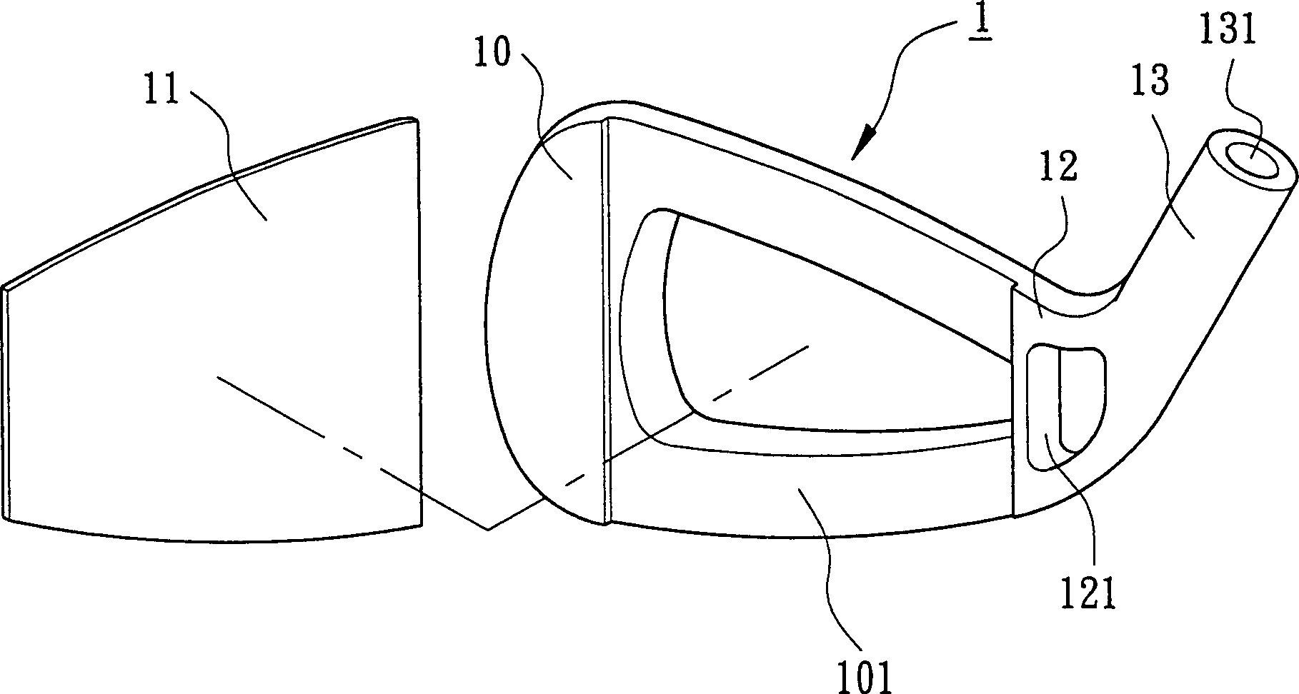
[0026] Such as image 3 , Figure 4 As shown, the golf club head 1 in which the connection part of the present invention forms a material escape hole is made of metal or alloy material, and it includes a club head body 10, a ball hitting face plate 11 for hitting a ball, a connection part 12 and a connecting part 12 to combine with the ball. The sleeve neck 13 of rod.
[0027] The front of the club head body 10 is provided with a joint portion 101 for the ball striking panel 11 to be embedded, pressed, brazed, welded, screwed or integrally formed.
[0028] The connecting portion 12 is connected between the ball striking panel 11 and the sleeve neck 13 , and an escape hole 121 is formed as a through hole or a blind hole.
[0029] When the escape hole 121 is a blind hole, the opening of the escape hole 121 is opened on the front or back of the golf club head 1 . The weight of the upper and lower halves of the connecting portion 12 can be uniformly reduced by the escape hole 1...
Embodiment 2
[0033] Such as Figure 5 , Figure 6 As shown, the golf club head 1a in which the connection part of the present invention forms a material escape hole is made of metal or alloy material, and it includes a club head body 10a, a ball-hitting face plate 11a for hitting a ball, a connection part 12a, and a connecting part 12a to combine with the ball. The collar 13a of the rod.
[0034] The front of the club head body 10a is provided with a joint portion for the ball striking panel 11a to be embedded, pressed, brazed, welded, screwed or integrally formed.
[0035] The connecting portion 12a is connected between the ball striking face plate 11a and the collar 13a, and a through hole or a blind hole is formed on the connecting portion 121a, and a small diameter portion 122a is formed for covering by the coating layer 20a. When the material escape hole 121a is a blind hole, the opening of the material escape hole 121a is opened on the front or back of the golf club head 1a.
[00...
Embodiment 3
[0040] Such as Figure 7 , Figure 8 As shown, the golf club head 1b in which the connection part of the present invention forms a material escape hole is made of metal or alloy material, and it includes a club head body 10ab, a ball hitting face plate 11b for hitting a ball, a connection part 12b, and a connecting part 12b to combine with the ball. The sleeve neck 13b of the rod.
[0041]The front of the club head body 10b is provided with a joint portion for the ball striking panel 11ba to be embedded, pressed, brazed, welded, screwed or integrally formed.
[0042] The connecting portion 12b is connected between the ball striking face plate 11b and the sleeve neck 13b, and is formed as a through hole or a blind hole for the material escape hole 121b, and forms a small diameter portion 122b covered by the coating layer 20b, and the small diameter portion 122b further extends to The collar 13b is extended to enlarge the small-diameter portion 122b. Thereby, the present inve...
PUM
 Abstract
Description
Claims
Application Information