
Starter for engine

An engine starting and motor shaft technology, which is applied in the directions of engine starting, electromechanical devices, engine components, etc., can solve problems such as shortening of clutch life and noise, and achieve the effect of suppressing noise.

Inactive Publication Date: 2006-09-13
MITSUBISHI ELECTRIC CORP
View PDF1 Cites 0 Cited by
  • Summary
  • Abstract
  • Description
  • Claims
  • Application Information

AI Technical Summary

Problems solved by technology

[0003] In the above-mentioned conventional engine starting device, since the output shaft of the clutch is mounted on the rotary shaft of the reduction gear arranged around the motor shaft, it is easy to be eccentric with respect to the motor shaft, and this eccentricity may shorten the life of the clutch.
[0004] In addition, the gear sound in the reducer may become noise

Method used


Image

  • Starter for engine
  • Starter for engine
  • Starter for engine

Examples


Embodiment 1

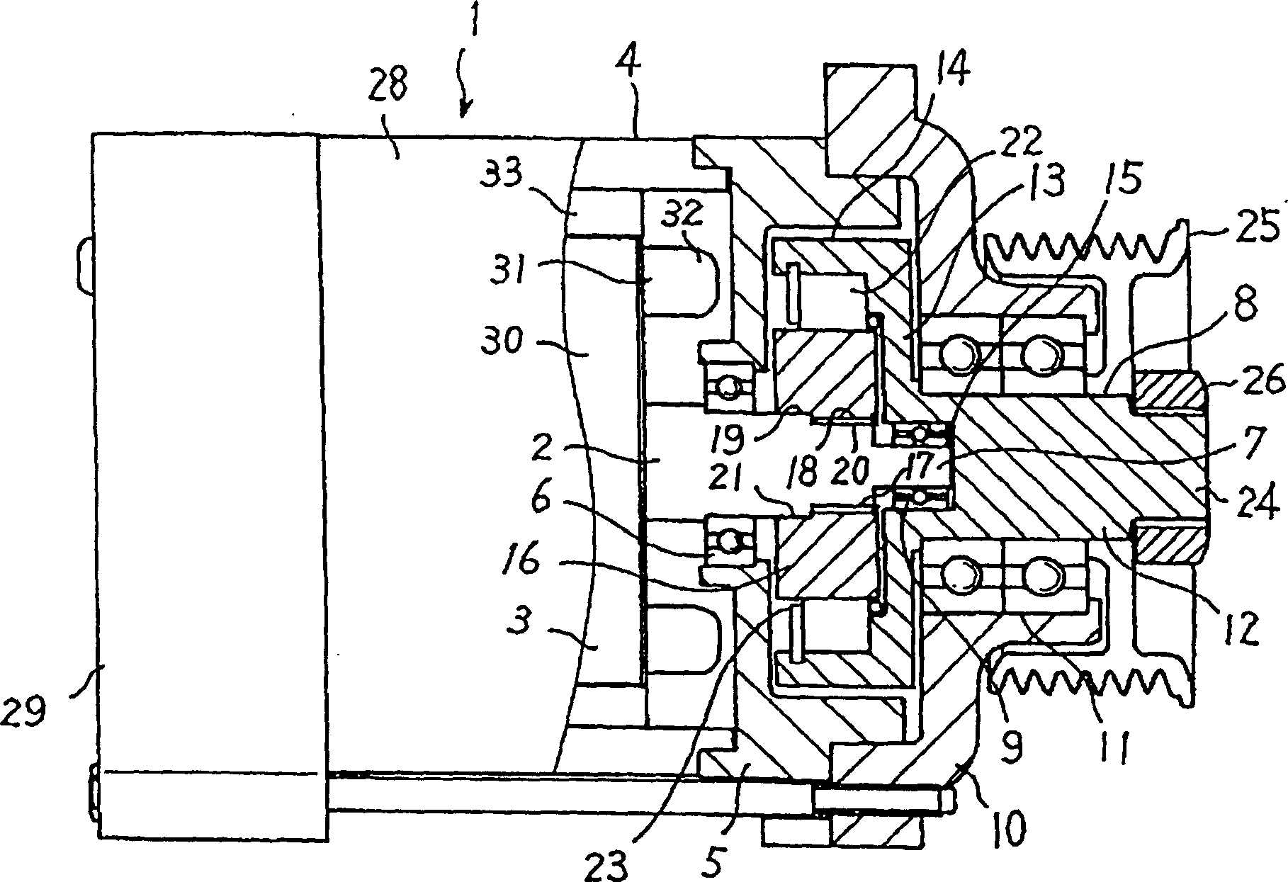
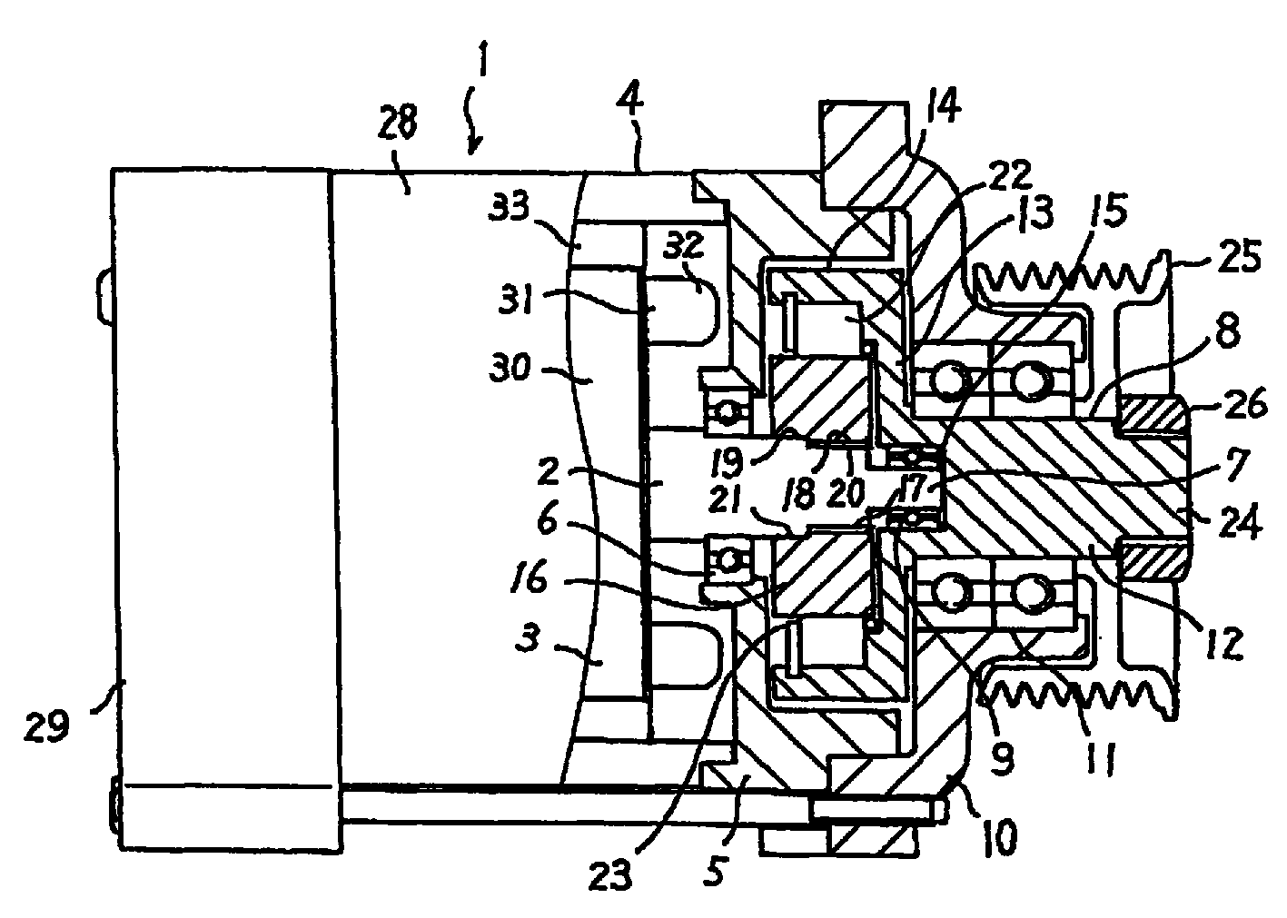
[0013] figure 1 It is a longitudinal sectional view showing the engine starting device according to Embodiment 1 of the present invention. In the figure, the motor 1 has a motor body 28 and a rotatable motor shaft 2 extending from the motor body 28 . The motor main body 28 has the armature 3 which rotates integrally with the motor shaft 2, and the stator 4 which surrounds the armature 3 with a gap. The motor shaft 2 is rotatably supported on the motor shaft bracket 5 through the bearing 6 . A motor shaft bracket 5 is mounted on the stator 4 .

[0014] In addition, the motor shaft 2 is also rotatably supported by a rear frame 29 arranged on the side opposite to the motor shaft bracket 5 of the motor 1 .

[0015] The armature 3 has an armature core 30 coaxially fixed to the motor shaft 2 and an armature coil 31 disposed on the outer peripheral portion of the armature core 30 . The armature coil 31 has a coil terminal 32 extending in the axial direction of the motor shaft 2 ....

Embodiment 2

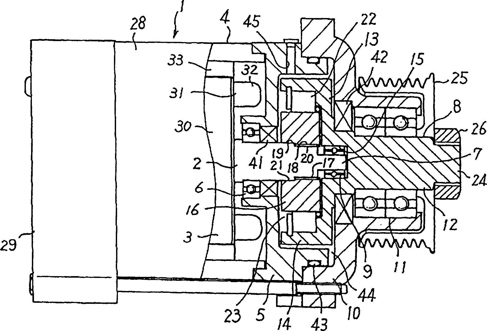
[0040] figure 2 It is a longitudinal sectional view showing an engine starting device according to Embodiment 2 of the present invention. In the figure, sealing members 41 and 42 are disposed between the motor shaft 2 and the motor shaft bracket 5, between the output shaft 8 and the output shaft bracket 10, and between the motor shaft bracket 5 and the output shaft bracket 10. , 43. The seal member 41 is disposed between the bearing 6 and the interior 16 . The seal member 42 is disposed between the bearing 11 and the extension 13 . The seal member 43 is disposed on a portion around the outer portion 14 where the motor shaft bracket 5 and the output shaft bracket 10 are fitted together.

[0041] Oil is stored in a space 44 surrounded by the motor shaft bracket 5 and the output shaft bracket 10 . Oil is stored at least to the extent that it impregnates a portion of the exterior 14 . Oil is prevented from leaking out by the sealing members 41 , 42 , and 43 . Furthermore, a...


PUM

PropertyMeasurementUnit
Outer diameteraaaaaaaaaa
Diameteraaaaaaaaaa
Diameteraaaaaaaaaa

Abstract

Provided is an engine starter capable of realizing long service life and reduction in noises. On the front end 7 of a rotatable motor shaft 2, an outer portion 14 disposed around the motor shaft 2 is provided, and an output shaft 8 coaxial to the motor shaft 2 is fitted so as to rotate. The output shaft 8 is always connected to an engine. On the motor shaft 2, an inner portion 16 rotating together with the motor shaft 2 is attached. Between the inner portion 16 and the outer portion 14, a sprag 22 for transmitting the rotation of the inner portion 16 to the outer portion 14 is disposed. The motor shaft 2 is rotatably journaled by a motor shaft bracket 5. Onto the motor shaft bracket 5, the output shaft bracket 10 is fitted so that the output shaft 8 may be coaxially journaled.

Description

technical field [0001] The present invention relates to, for example, an engine starting device for starting an engine of an automobile or the like. Background technique [0002] In conventional engine starters, the rotation of the motor shaft is transmitted to the clutch through the planetary reducer. The rotary shaft of the planetary reducer is arranged around the motor shaft. The clutch is installed on the rotary shaft of the planetary reducer, and the output shaft of the clutch is in a coaxial state with the motor shaft (refer to Japanese Patent Application Laid-Open No. 2001-99197). [0003] In the above-mentioned conventional engine starting device, since the output shaft of the clutch is mounted on the rotary shaft of the reduction gear arranged around the motor shaft, it is easy to be eccentric with respect to the motor shaft, and this eccentricity may shorten the life of the clutch. . [0004] Also, the gear sound in the reducer may become noise. [0005] In ord...

Claims


Application Information

Patent Timeline
IPC IPC(8): F02N15/02F02N11/00F02N15/06H02K7/108H02K7/18
CPCF02N15/066F02N15/025F02N2250/08F02N15/02
Inventor 马场秀和北村裕城山繁
Owner MITSUBISHI ELECTRIC CORP
Learn More