
Photoconductor drum, drive shaft, photoconductor drum system, image-forming apparatus, and multifunction apparatus

一种感光体鼓、驱动轴的技术,应用在应用电荷图形的电记录工艺、应用电荷图形的电记录工艺的设备、光学等方向,能够解决影响振摆精度等问题,达到容易插拔的效果

Active Publication Date: 2019-05-17
SHARP KK
View PDF17 Cites 0 Cited by
  • Summary
  • Abstract
  • Description
  • Claims
  • Application Information

AI Technical Summary

Problems solved by technology

However, in order to transmit the drive, the parallel pin provided on the drive shaft must be inserted into the pin insertion hole on the flange side. In this method, there will be problems due to the positional accuracy of the parallel pin and the pin insertion hole on the flange side. Rotational vibration of the photosensitive drum
In addition, in order to facilitate insertion and removal, a certain amount of clearance is required between the flange and the drive shaft, but there are cases where vibration accuracy is affected by rattling caused by this clearance.

Method used


Image

  • Photoconductor drum, drive shaft, photoconductor drum system, image-forming apparatus, and multifunction apparatus
  • Photoconductor drum, drive shaft, photoconductor drum system, image-forming apparatus, and multifunction apparatus
  • Photoconductor drum, drive shaft, photoconductor drum system, image-forming apparatus, and multifunction apparatus

Examples


no. 1 Embodiment approach

[0079] Embodiments of the present invention will be described in detail below.

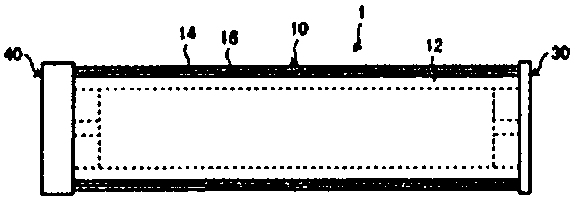
[0080] figure 1 A schematic diagram of the photoreceptor drum of this embodiment is shown in .

[0081] like figure 1 As shown, the photoreceptor drum 1 includes a drum main body 10, front flanges (hereinafter referred to as "F flanges") 30 fitted to both ends of the drum main body 10, and rear flanges (hereinafter referred to as "R flanges"). 40.

[0082] The drum main body 10 includes a cylindrical conductive support 12 , an intermediate layer (also referred to as “primer layer”) 16 coated on its outer peripheral surface, a photosensitive layer 14 , and the like. The F flange 30 is a flange located on the front (F) side in a state where the photoreceptor drum 1 is mounted on the image forming apparatus. The R flange 40 is a flange located on the rear (R) side of the image forming apparatus in which the driving system of the image forming apparatus is disposed in the aforementioned state. He...

Embodiment 1

[0199] The shaft support portion of the flange of Example 1 adjusted the diameter of the inner peripheral surface so that a gap of 20 micrometers was generated between the inner peripheral surface thereof and the outer peripheral surface of the drive shaft. Table 1 is a list of conditions and evaluation items of Examples 1 to 5 and Comparative Examples 1 to 5. Additionally, if Figure 11A As shown in Table 1, three fitting protrusions with a height of 40 μm were provided at uniform angles along the circumferential direction on the inner peripheral surface.

[0200] [Table 1]

[0201]

[0202]

Embodiment 2

[0204] The shaft support portion of the flange of Example 2 was the same as that of Example 1, and the diameter of the inner peripheral surface was adjusted so that a gap of 20 μm was formed between the inner peripheral surface and the outer peripheral surface of the drive shaft. Additionally, if Figure 11B As shown in Table 1 and Table 1, in Example 1, two sets of fitting protrusions with a height of 40 μm provided on the shaft supporting portion are provided in two sets in the axial direction.


PUM


Abstract

The invention provides a photoconductor drum which is not liable to be eccentric and is easy to plug. The photoconductor drum includes a drum body that is cylindrical, and a pair of flanges fitted toor near two axial ends of the drum body, wherein at least one of the flanges includes a plurality of engagement protrusions disposed on an inner circumferential surface of a through-hole for insertinga drive shaft for drivingly rotating the photoconductor drum, the through-hole having a larger radius than the drive shaft.

Description

technical field [0001] The present invention relates to a photoreceptor drum, a drive shaft, a photoreceptor drum system including the photoreceptor drum and the drive shaft, an image forming apparatus and a compound machine including the photoreceptor drum system. Background technique [0002] An electrophotographic image forming device includes a cylindrical photosensitive drum that rotates around an axis, a charging device arranged around it, an exposure device, a developing device, a transfer roller, etc. The surface of the photoreceptor drum temporarily charged by the charging device forms a latent image, and a toner image according to the latent image is formed by the developing device, and the toner image is passed between the photoreceptor drum and the transfer roller to be transferred by the transfer belt print. Then, the image is transferred from the transfer belt to a recording medium such as paper, and the image is fixed to the recording medium by a fixing devic...

Claims


Application Information

Patent Timeline
Patent Type & Authority Applications(China)
IPC IPC(8): G03G15/00
CPCG03G15/757G03G21/1647G03G15/751B65H27/00F16C13/00
Inventor 马场公希松尾力也
Owner SHARP KK
Learn More