
A double-sided transmission rotary tiller

A technology of rotary tiller and transmission mechanism, which is applied in the direction of tillage implements, agricultural machinery and implements, etc. It can solve the problems of affecting the service life, the transmission mechanism is brought into the soil, and the transmission mechanism is heavy, so as to achieve reliability and service life Lifting, surface rotary tillage is even and level, and the effect of improving work efficiency

Active Publication Date: 2016-09-28
GANSU TAOHE TRACTOR MFG
View PDF11 Cites 0 Cited by
  • Summary
  • Abstract
  • Description
  • Claims
  • Application Information

AI Technical Summary

Problems solved by technology

[0003] At present, the power transmission methods of rotary tillers are mainly: intermediate transmission and single-side transmission. The transmission mechanism of the intermediate transmission method is arranged in the middle of the frame. After working for a period of time, the transmission mechanism will be brought into the soil, which will affect the service life.
The transmission mechanism of the single-side transmission mode is arranged on the side wall of the frame to avoid soil intrusion. The transmission mechanism of some large-scale rotary tillage equipment is heavy, and eccentricity is prone to occur during use, and the surface of the rotary tillage is uneven.
At the same time, the wheelbase of the power shaft is long, which requires a large tractor to drive, which consumes a lot of driving energy and has low working efficiency.

Method used


Image

  • A double-sided transmission rotary tiller
  • A double-sided transmission rotary tiller

Examples


Embodiment Construction

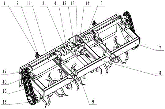
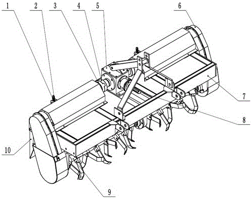
[0014] Such as figure 1 A double-sided transmission rotary cultivator shown includes a gearbox 5, a transmission mechanism, a rotary tiller blade 9, a scraper 10 and a frame 7, the transmission mechanism is located in the middle of the frame 7, and the transmission mechanism includes an output shaft 14 and the input shaft 11, the input shaft 11 is arranged on both sides of the output shaft 14 respectively, one end of the two input shafts 11 is respectively connected with the two ends of the output shaft 14, and the other end of the input shaft 11 is connected with the drive sprocket 17; the rotary tiller 9 Located at the front lower part of the frame 7, the rotary tiller 9 is connected with the driven sprocket 15 on the side of the frame 7, and the driving sprocket 17 and the driven sprocket 15 are connected by a chain 16. The two ends of the output shaft 14 are respectively provided with a docking groove 4, and one end of the input shaft 11 is provided with a docking groove 4...


PUM


Abstract

The invention relates to the technical field of agricultural machinery, in particular to a double-side transmission rotary tiller. The drive shaft of the present invention transmits power to the gearbox, and the bevel gear at one end of the drive shaft with bevel gear on the output shaft Engaging, the power is transmitted to the output shaft, and the output shaft simultaneously drives the driving sprocket of the input shaft on both sides to rotate, and the power is transmitted to the passive sprocket through the chain, thereby driving the rotary tillage mechanism to work. The geometric center and the center of gravity of the tool coincide, which makes the operation more stable. At the same time, the size of the transmission shaft is effectively reduced, and the driving force can be quickly transmitted to the rotary tillage executive parts, which improves the work efficiency. The above-mentioned transmission mode on both sides is especially suitable for large rotary tillage equipment. , the transmission is more stable, less prone to eccentricity, and the surface of the rotary tillage is more even and smooth. Two ends of the output shaft are respectively provided with docking grooves, one end of the input shaft is provided with a docking groove, and the docking grooves of the output shaft and the docking grooves of the input shaft are connected by a cross slider. Power transmission reliability and service life are greatly improved.

Description

technical field [0001] The invention relates to the technical field of agricultural machinery, in particular to a double-side transmission rotary tiller. Background technique [0002] A rotary tiller is a cultivating machine whose working parts actively rotate and process soil with the principle of milling. At present, there are many kinds of rotary tillers in China, and the implements are used together with four-wheel tractors. In some areas, they are used as farming machines, and some are used as land preparation machines. The application volume in our country is increasing year by year, especially in the northern arid areas. Its structure includes frame, transmission system, rotary tillage device, soil retaining board, leveling scraper and so on. The power input shaft transmits power to the gearbox, drives the output shaft, and the output shaft transmits the power to the rotary tiller through the transmission system, thereby driving the rotary tiller to work. The blades ...

Claims


Application Information

Patent Timeline
Patent Type & Authority Patents(China)
IPC IPC(8): A01B33/08A01B33/12
Inventor 龚建成马明义赵新平王钧田琳刘晓丽马进
Owner GANSU TAOHE TRACTOR MFG
Learn More