

Electromagnetic tripping apparatus in circuit breaker
An electromagnetic tripping and circuit breaker technology, applied in electromagnetic release switches, emergency protection devices, circuits, etc., to achieve the effect of reliable tripping action
- Summary
- Abstract
- Description
- Claims
- Application Information
AI Technical Summary
Problems solved by technology
Method used
Image

Examples
Embodiment Construction
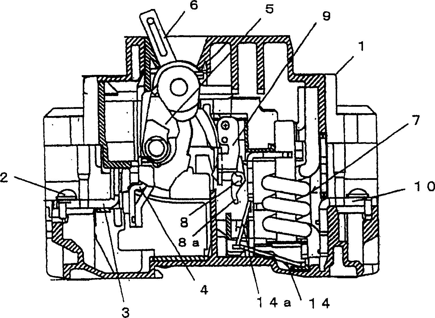
[0023] The following will refer to figure 1 and 2 The examples shown describe embodiments of the invention. exist figure 1 in, with Figure 5 The same parts are denoted by the same reference numerals, and their descriptions are omitted.
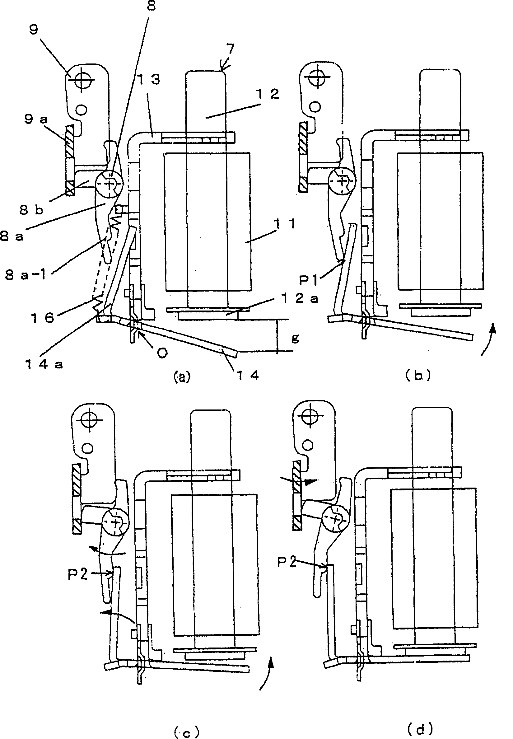
[0024] figure 1 The electromagnetic trip unit shown in the example is basically the same as Figure 5 The structure shown is the same, but the trip arm 8a extending downward from the trip bar 8 and facing the side of the operating arm 14a of the electromagnet unit 7 has been changed in shape as described below. also, figure 1 (a) to 1(d) respectively show the Figure 5 Action states corresponding to (a) to 5(d).
[0025] In other words, the arm end of the tripping arm 8a in the example shown in the accompanying drawings faces the operating arm 14a standing upright from the bottom up, and the length of the tripping arm 8a is set to face the longitudinal direction of the operating arm 14a. After the center part (in the Figure 5 I...
PUM
 Abstract
Description
Claims
Application Information