
Information regenerating device

A reproduction device and information recording technology, applied in the direction of information storage, recording information storage, using detectable carrier information, etc., can solve the problem of not describing the method of recording signals and data efficiently

Inactive Publication Date: 2006-10-25
HITACHI CONSUMER ELECTRONICS CORP
View PDF0 Cites 0 Cited by
  • Summary
  • Abstract
  • Description
  • Claims
  • Application Information

AI Technical Summary

Problems solved by technology

According to these documents, although compressed video and audio signals are recorded on media in data applications, and computer user data is recorded therein, any method of efficiently recording signals and data on media has not been described

Method used


Image

  • Information regenerating device
  • Information regenerating device
  • Information regenerating device

Examples


Embodiment Construction

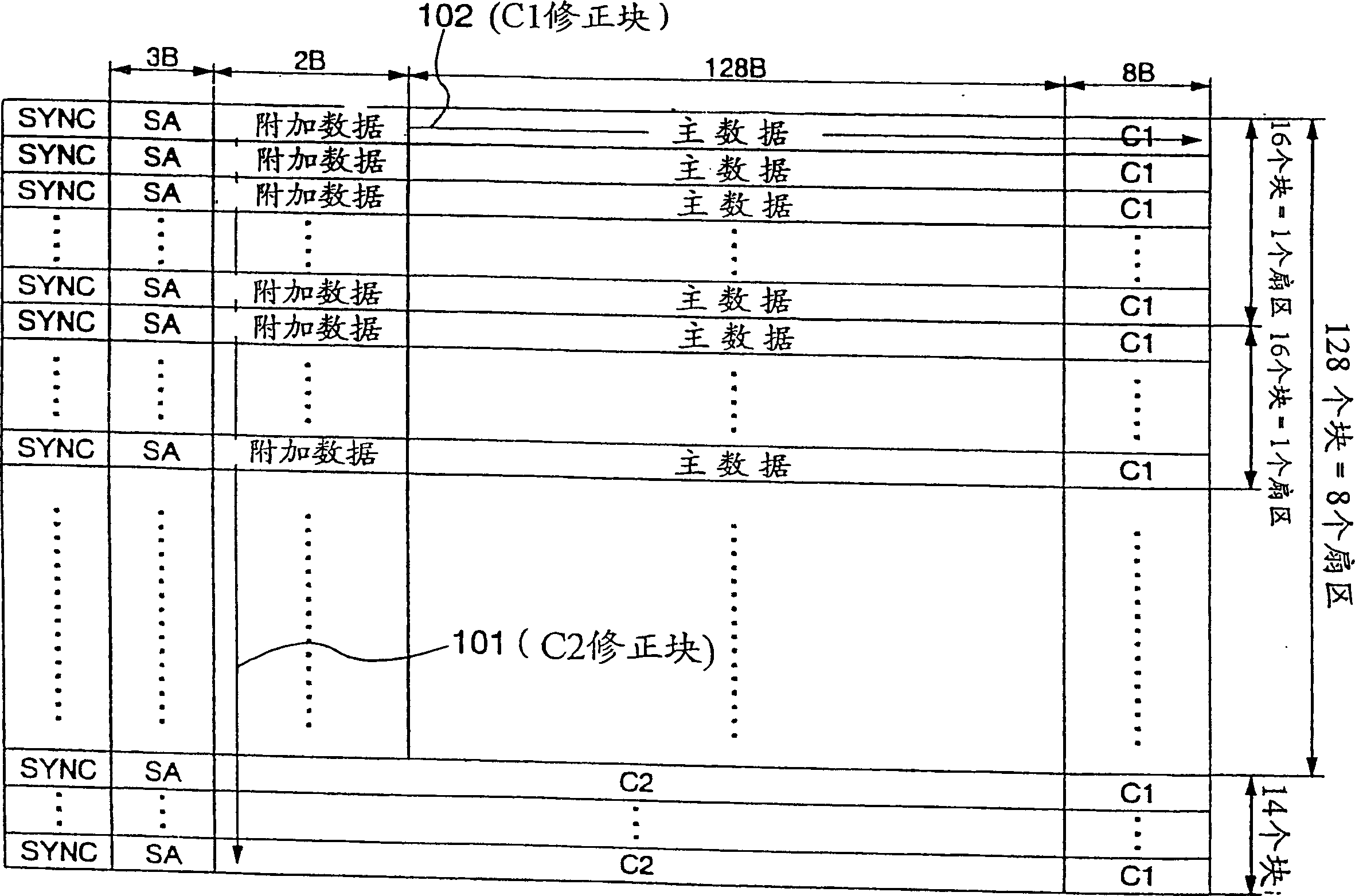
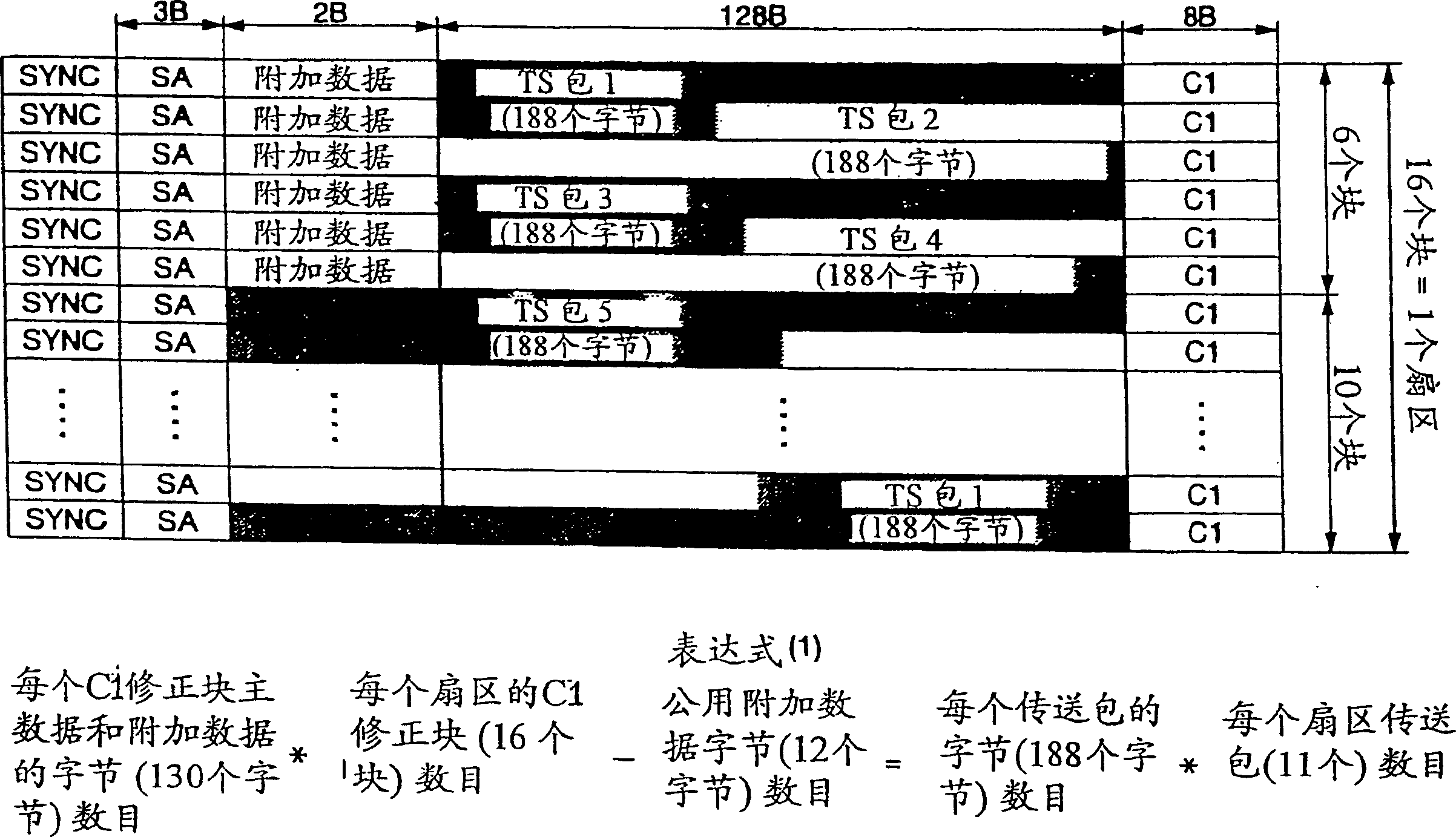
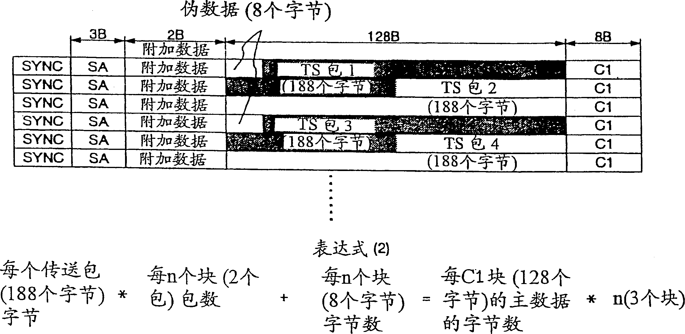
[0019] refer to figure 1 The first embodiment of the present invention will be described. figure 1 is the recording format of recording information in the first embodiment of the present invention. This figure specifies the data arrangement of a correction block. exist figure 1 Among them, SYNC represents a synchronization signal, which specifies the first position of the SYNC block, SA represents a sector address, which specifies a value assigned to a sector, and additional data is appended to the main data to indicate, for example, the characteristics of the main data "main data" is the main record information, C2 represents the second error correction code (hereinafter abbreviated as C2 code) added to the additional data and main data, and C1 represents the first error correction code added to the additional data and main data code (hereinafter abbreviated as C1 code). Divide the main data input at one timing into 128 bytes ( figure 1 represented as 128B) units and...


PUM


Abstract

In a system that records compressed video and audio signals and computer user data in units of magnetic disk sectors, in order to reproduce data at high speed in a simple manner, data recorded in a magnetic disk is layered into data in predetermined units so that each A final data is augmented with a first error correction (C1) code, forming a (C1) correction block. Sectors are generated, each sector comprising a number (C1) of correction blocks. Added to each (C1) correction block is a sector-identifying code. A second error correction (C2) code is added to all data in multiple (C1) correction blocks to record the final data in the disk so that interleaving and deinterleaving can be done in one block. The capacity of each sector is set substantially equal to the capacity of a plurality of transfer packets.

Description

technical field [0001] The present invention relates to an apparatus for recording and / or compressing video and audio signals and / or computer application data on a recording medium such as an optical disc. Background technique [0002] An optical disc dedicated to reproducing a stored signal has been described in detail in "CD-From Audio to Personal Computer" by Kenji Hayashi, published in Japanese by Corona Ltd. on July 25, 1990. In Hiroshi Fujiwara. Compressed video and audio signals are described in detail in the Japanese document "New Moving Picture Special Group (MPEG) Text" published by ASCI IL Ltd. on August 1, 1994. [0003] In the previous article, in order to add error correction codes to data written consecutively on a compact disk (CD) in advance, a CD error correction method has been described, in which the first and second error correction codes are added And by changing the amount of delay associated with the first and second correction codes for each data, ...

Claims


Application Information

Patent Timeline
Patent Type & Authority Patents(China)
IPC IPC(8): G11B20/10H04N5/91G11B7/00G11B7/004G11B11/10G11B11/105G11B20/12G11B20/18G11B27/30H04N5/783H04N5/85H04N9/804
CPCG11B20/1254G11B20/1809G11B27/3027G11B2020/1222G11B2020/1232G11B2020/1267G11B2020/1287G11B2020/1288G11B2220/20G11B2220/213G11B2220/2545H04N5/783H04N5/85H04N9/8042G11B20/12
Inventor 永井裕中村雅文竹内敏文平林正幸
Owner HITACHI CONSUMER ELECTRONICS CORP
Learn More