Joint especially for daybeds

A head and function technology, applied in the direction of connection, application, household appliances, etc., can solve the problem that the function is not always guaranteed to be reliable, and achieve the effect of simple manufacturing and easy installation

Inactive Publication Date: 2006-11-22
RAUSCHENBERGER METALLWAREN
View PDF0 Cites 2 Cited by
  • Summary
  • Abstract
  • Description
  • Claims
  • Application Information

AI Technical Summary

Problems solved by technology

In the known couch joints, the feet are first turned out and the head is then swiveled relative to the rest of the couch, but this function is not always guaranteed to be reliable; had to fold back again and put the foot in its supporting position

Method used


Image

  • Joint especially for daybeds
  • Joint especially for daybeds
  • Joint especially for daybeds

Examples


Embodiment Construction

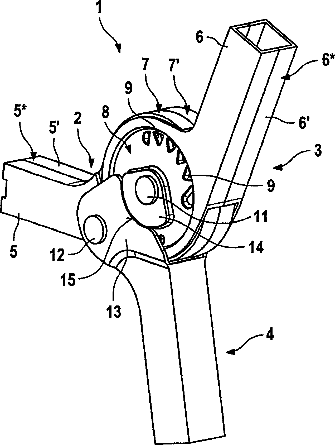
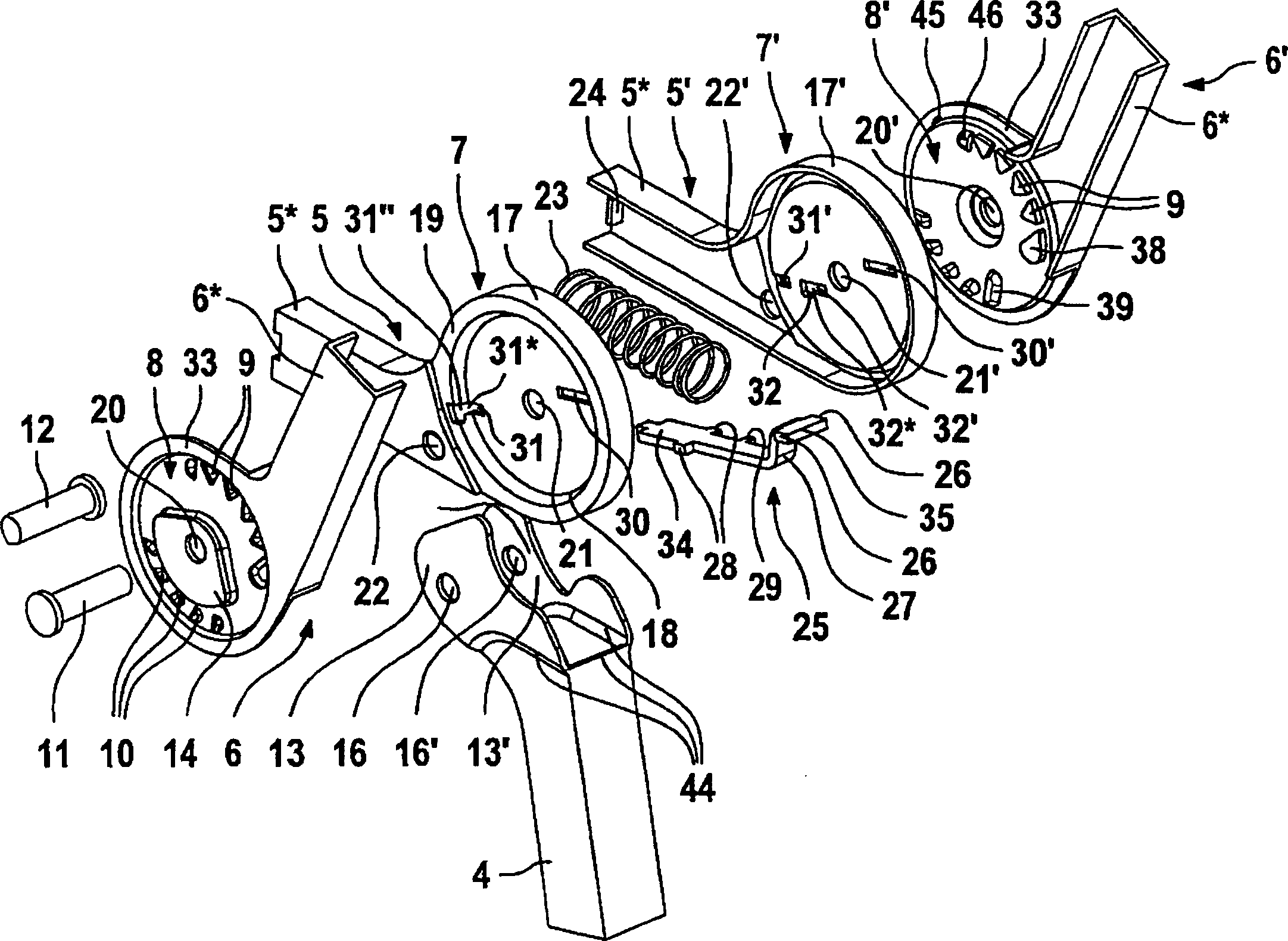
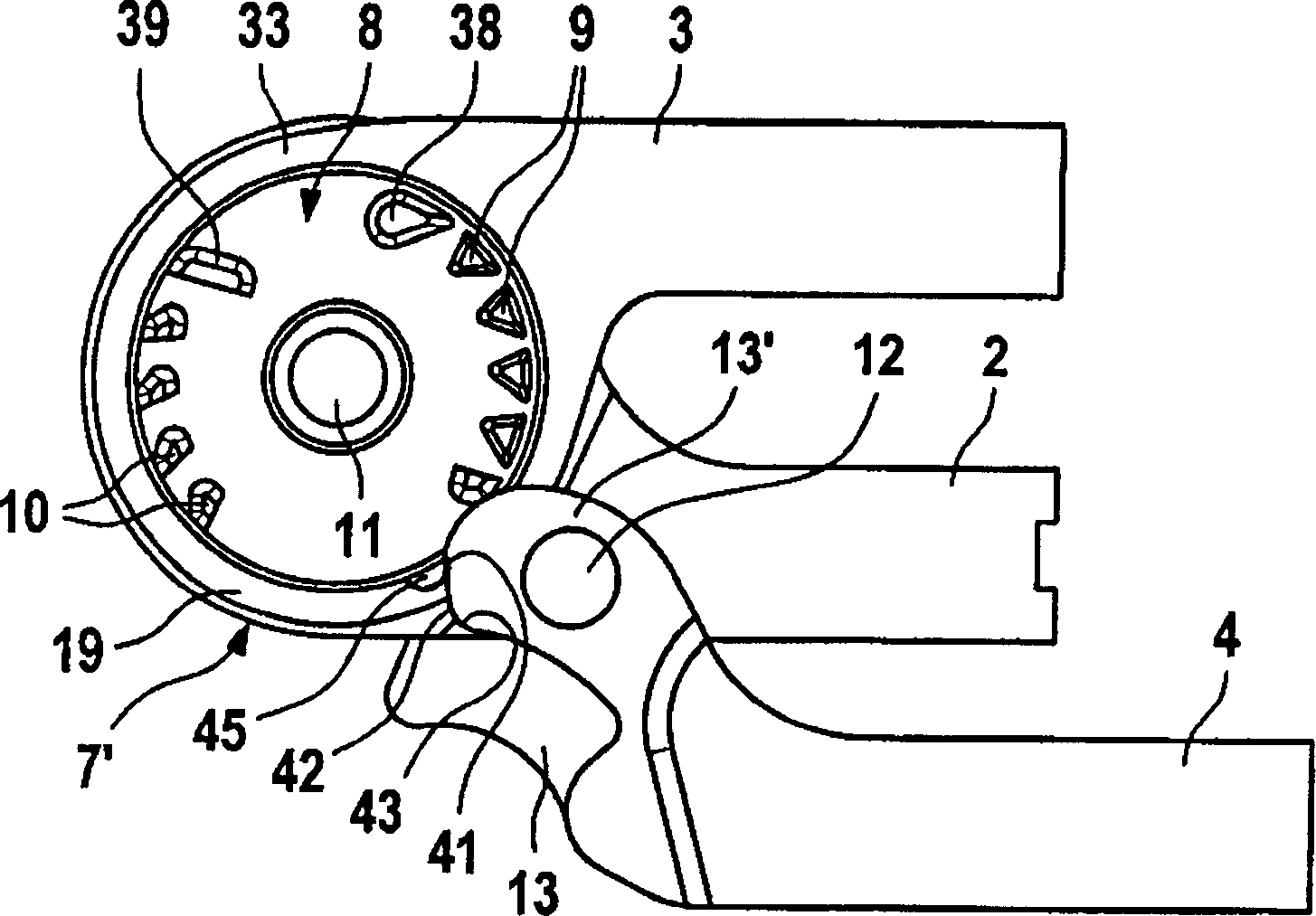
[0024] exist figure 1 A perspective view of a couch joint 1 in the use position is shown in . The couch joint 1 comprises a middle part 2, a head 3 and a foot 4, wherein the "foot" here refers to the upright of the couch. The middle part 2 consists of two shaped parts, namely a first pair of shaped parts 5, 5', embodied in the present embodiment as profiled sheet metal parts. The first pair of shaped parts 5, 5' comprises an inner shell 7, 7' constituting a strut 5 in an elongated portion * . The head 3 consists of two shaped parts, namely a second pair of shaped parts 6, 6', here likewise embodied as profiled sheet metal parts, which each comprise a housing 8, wherein the elongated sides of the second pair of shaped parts 6, 6' Sections form a pillar 6 * . The housing 8 is provided with a plurality of embossments, which form first projections 9 pointing inward, which will be described in more detail below with reference to the other figures. The inner shells 7, 7' and t...


PUM


Abstract

The pivot comprises two outer shells (8, 8') attached to the halves of a head rest upright (6*). Inner shells (7, 7') are attached to halves of a side member (5*) of the bed. Inwardly-projecting lugs (9) on the outer shells cooperate with pins (26, 28) on a spring-loaded slide (25) between the inner shells to lock the head rest at different positions.

Description

technical field [0001] The present invention relates to a joint, especially for a couch such as a couch or a camp bed, which joint has a middle part and a head. Background technique [0002] The couch joint is used to articulate a head with a couch frame and to pivotably support a foot serving as a pillar on the couch frame. The head should be able to be adjusted to be located at multiple angular positions relative to other surfaces of the couch. In the known couch joints, the feet are first turned out and the head is then swiveled relative to the rest of the couch, but this function is not always guaranteed to be reliable; Had to fold back again and put the foot on its support. Contents of the invention [0003] The object of the present invention is to provide a joint, especially for a couch, which is simple in structure and reliable in operation. [0004] This task is achieved by a joint with a middle part and a head, where the head and the middle part each consist o...

Claims


Application Information

Patent Timeline
Patent Type & Authority Patents(China)
IPC IPC(8): A47C20/00A47C20/04
CPCA47C1/026A47C20/043Y10T403/32352Y10T403/32336
Inventor J·劳森伯格M·鲍姆盖尔特·盖尔
Owner RAUSCHENBERGER METALLWAREN
Why Eureka
Try Eureka