Multi-directional self-aligning shear type electromagnetic lock

A technology of electromagnetic lock and shearing type, which is applied in the direction of building locks, devices for fastening carpets, mechanical equipment, etc.

Inactive Publication Date: 2001-02-28
HANCHETT ENTRY SYST
View PDF4 Cites 8 Cited by
  • Summary
  • Abstract
  • Description
  • Claims
  • Application Information

AI Technical Summary

Problems solved by technology

It is believed that there has been no electric lock to date that would a

Method used


Image

  • Multi-directional self-aligning shear type electromagnetic lock
  • Multi-directional self-aligning shear type electromagnetic lock
  • Multi-directional self-aligning shear type electromagnetic lock

Examples


Embodiment Construction

[0036] Detailed Description of Preferred Embodiments

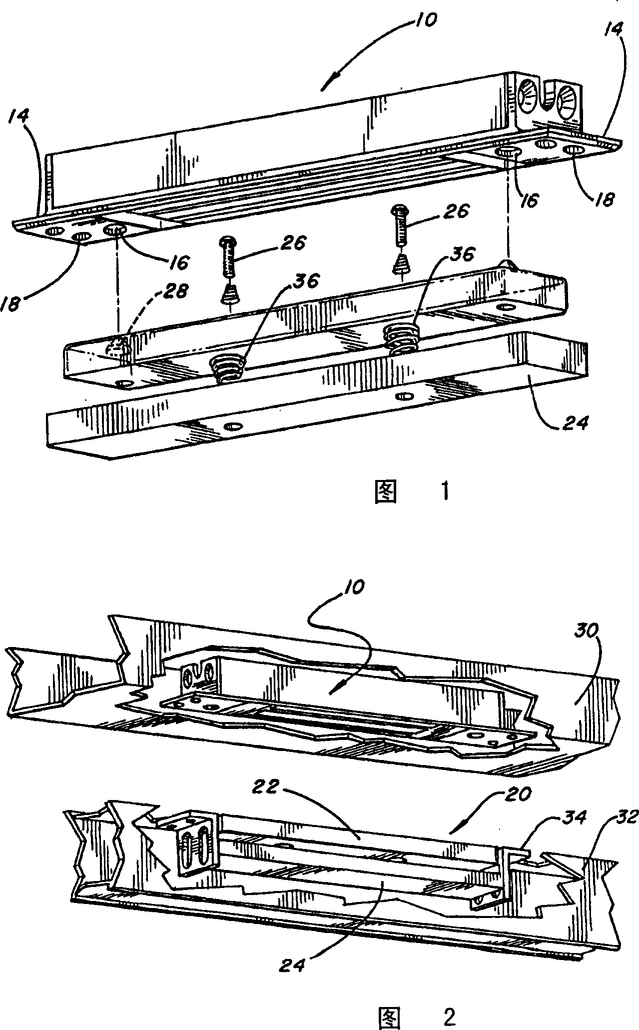
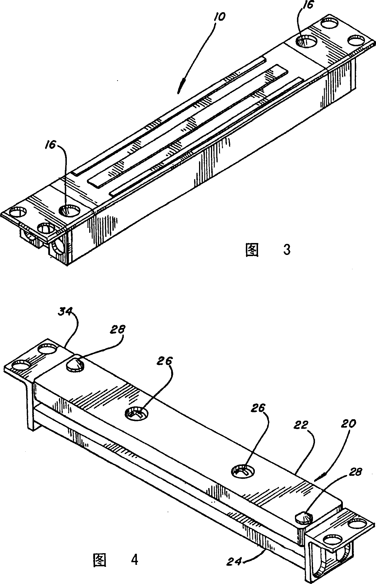
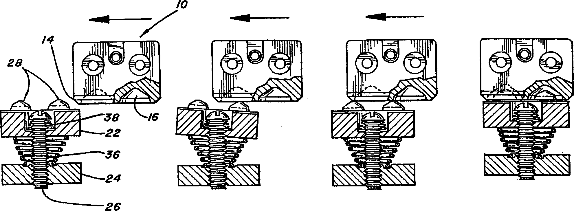
[0037] Figure 1 shows the main components of a preferred embodiment of the invention. The solenoid assembly 10 includes an E-shaped core structure 12 and metal protrusions 14 at each end, as is well known in the industry. Each metal protrusion 14 includes a conical recess 16 and a plurality of mounting holes 18 . The armature assembly includes an armature 22 attached to a base plate 24 by fasteners such as screws 26, bolts or the like. The conical projecting bosses 28 fit within corresponding conical recesses 16 when the lock is engaged.

[0038] FIG. 2 shows the situation that the electromagnet assembly and the armature assembly are installed on the door frame 30 and the door 32 respectively. The door frame receives the electromagnet assembly 10 , and the electromagnet assembly is fixed through the mounting holes 18 thereof with screws. The armature 22 and base plate 24 are similarly mounted within the door with suita...


PUM


Abstract

A shear-type electromagnetic lock is disclosed whose armature can approach the electromagnet from any transverse direction, which can be mounted in any orientation with respect to gravity, and which does not require any door position sensing means. The armature includes a pair of standoffs in the form of conically projecting buttons affixed thereto, the buttons projecting from the plane of contact between the armature and the electromagnet. The buttons have a base angle of 60-80 degrees adjacent the armature, and an angle of 45 degrees distal from the armature, and terminate in a smoothly rounded point. The armature is mounted to a sub-plate via counteracting springs such that the armature "floats" on the sub-plate, with the distance between the armature and the sub-plate being adjustable via adjusting screws. A matching electromagnet assembly for mounting to a door frame includes matching conical depressions positionally corresponding to the conical buttons such that the buttons seat into the depressions when the armature and electromagnet are properly aligned. The buttons and recesses are arranged in a staggered pattern.

Description

field of invention [0001] The present invention relates to the field of electromagnetic door locks, more particularly to the field of shearing type electromagnetic locks. Background of the invention [0002] "Traditional" electromagnetic locks are mounted so that the face of the electromagnet is in the same plane as the face of the door. The electromagnet is mounted on the door frame and the armature plate is mounted on the door. When the door is closed, the armature plate is directly butted against the surface of the electromagnet, and the door is fastened by electromagnetic force. In the industry, this is sometimes referred to as a "straight pull" magnetic lock. [0003] There is also a special electromagnetic lock called a "shear lock". The face of the electromagnet of this lock is perpendicular to the face of the door. When the armature plate is fixed to the electromagnet, a sliding force is applied to the electromagnetic joint in order to open the door. This door s...

Claims


Application Information

Patent Timeline
IPC IPC(8): E05B65/10E05C19/16
CPCY10S292/53Y10S292/61E05B65/102E05C19/166Y10S292/55Y10T292/11
Inventor T·E·罗斯V·J·弗拉里希尔迪
Owner HANCHETT ENTRY SYST
Why Eureka
Try Eureka