Focusing control method for optical disc

A focus control, optical disc technology, used in optical recording/reproducing, optical recording heads, beam guides, etc., and can solve problems such as optical heads not being optimal

Inactive Publication Date: 2006-12-06
LITE ON IT
View PDF0 Cites 0 Cited by
  • Summary
  • Abstract
  • Description
  • Claims
  • Application Information

AI Technical Summary

Problems solved by technology

[0012] However, due to the error of the closed-loop servo system itself, the position of the optical head of the known optical drive is not the optimal position when the focus error signal is zero.

Method used


Image

  • Focusing control method for optical disc
  • Focusing control method for optical disc
  • Focusing control method for optical disc

Examples


Embodiment Construction

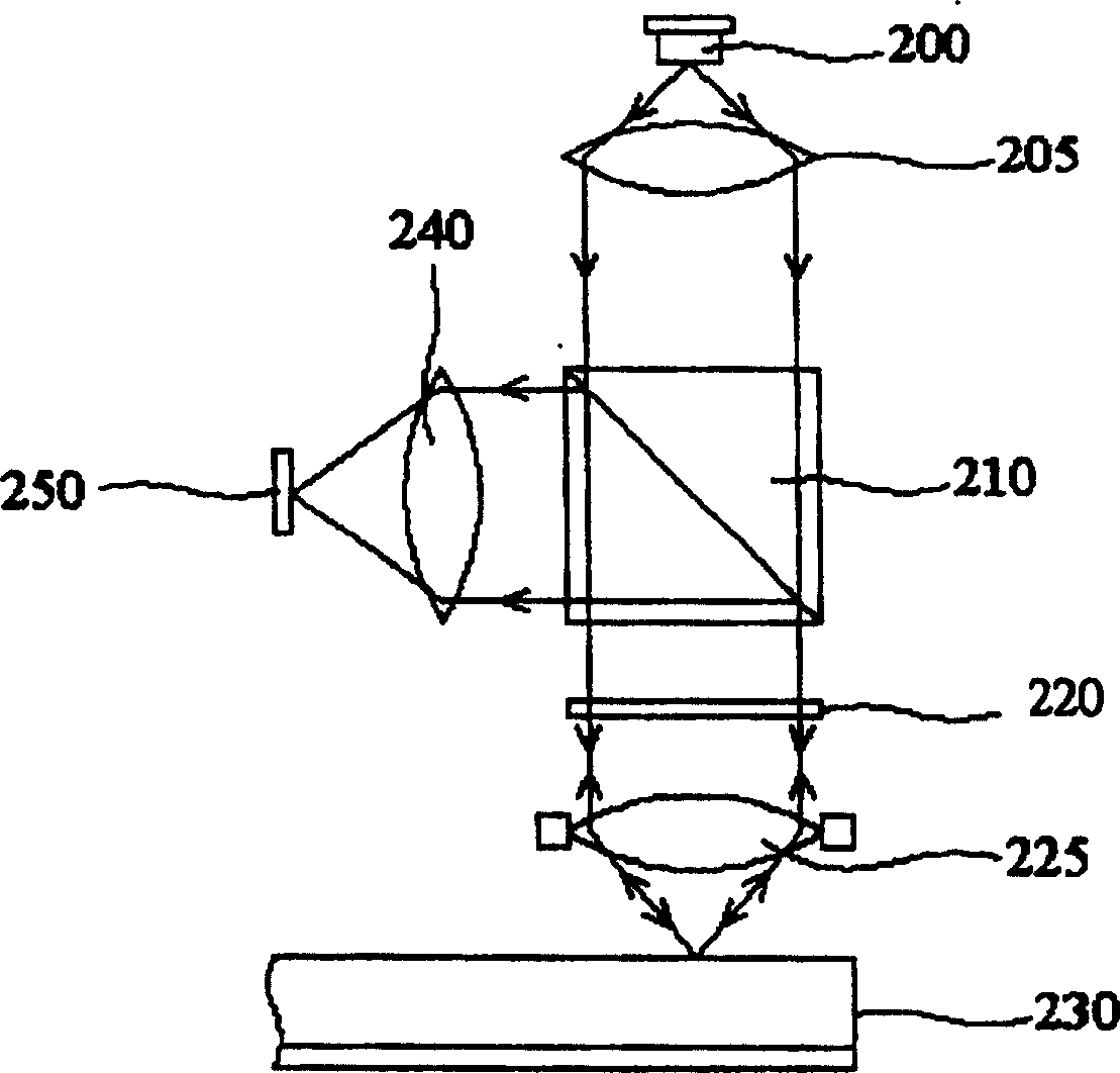
[0026] Generally speaking, the spiral track on the reflective layer of the optical disc will record information of varying brightness and darkness, and the information will be focused on the photodetector through the reflected laser beam. The light intensity received by the light detection unit on the photodetector is summed and converted into an electrical signal to become a high-frequency signal (HF signal). After the optical drive decodes the high-frequency signal, the data recorded on the optical disc can be obtained. Generally speaking, the amplitude of the high-frequency signal is related to the focus of the optical head. For example, if the focus of the optical head is just on the reflective layer, the amplitude of the high-frequency signal will be the largest at this time, and the quality of the high-frequency signal It is also the best; on the contrary, if the focus of the optical head is not located on the reflective layer, the amplitude of the high-frequency signal a...


PUM


Abstract

The present invention is a focus control method of an optical disc, comprising the following steps: using a closed-loop servo system to control an optical head in a linear region of a focus error signal; providing n bias compensation voltages to be superimposed on the focus error signal , and obtain the corresponding n swing information state count values, wherein, each swing information state count value is superimposed on the focus error signal by using a bias compensation voltage, so that after the optical head moves a distance, a fixed The sampling frequency samples a wobble information within a fixed time and counts a decoded message to obtain the wobble information state count value; select the wobble information state count value with the largest value from the n wobble information state count values ​​and its corresponding A specific bias compensation voltage; and the specific bias compensation voltage is continuously superimposed on the focus error signal, so that the focus of the optical head can be stably focused on the reflective layer of the optical disc, and the quality of the optical drive signal is greatly improved.

Description

technical field [0001] The present invention relates to a focusing control method of an optical disc, and in particular relates to a method for correctly focusing the focal point of the laser beam emitted by the optical head on the reflective layer of the optical disc. Background technique [0002] Please refer to figure 1 , which shows the optical head reading system of the optical drive. Wherein, the laser diode 200 outputs a laser beam, and the beam passes through the collimating lens 205 , the polarized beam splitter 210 , the 1 / 4 wavelength plate 220 , and the collecting lens 225 to reach the optical disc 230 . The light beam reflected from the optical disk passes through the collecting lens 225 , the 1 / 4 wavelength plate 220 , the polarized beam splitter 210 , and the lens 240 , and is projected to the photodetector 250 . [0003] And because of the different types of optical discs, the distance between the reflective layer (Reflecting Layer) and the optical head rea...

Claims


Application Information

Patent Timeline
Patent Type & Authority Patents(China)
IPC IPC(8): G11B7/09G11B7/135G11B7/095
Inventor 徐正煜傅仁杰李敦介
Owner LITE ON IT
Why Eureka
Try Eureka