Automatic oiling device for CD driver screw rod

A driving device and screw technology, applied in the direction of optical recording head, reducing the physical parameters of the carrier, etc., can solve the problems of lubricating oil waste, unable to oil the thread, insufficient lubrication, etc.

Inactive Publication Date: 2007-01-31
PEGATRON
View PDF2 Cites 0 Cited by
  • Summary
  • Abstract
  • Description
  • Claims
  • Application Information

AI Technical Summary

Problems solved by technology

However, the above-mentioned traditional oiling steps can only oil the entire lead screw, but cannot oil the thread. T...

Method used


Image

  • Automatic oiling device for CD driver screw rod
  • Automatic oiling device for CD driver screw rod
  • Automatic oiling device for CD driver screw rod

Examples


Embodiment Construction

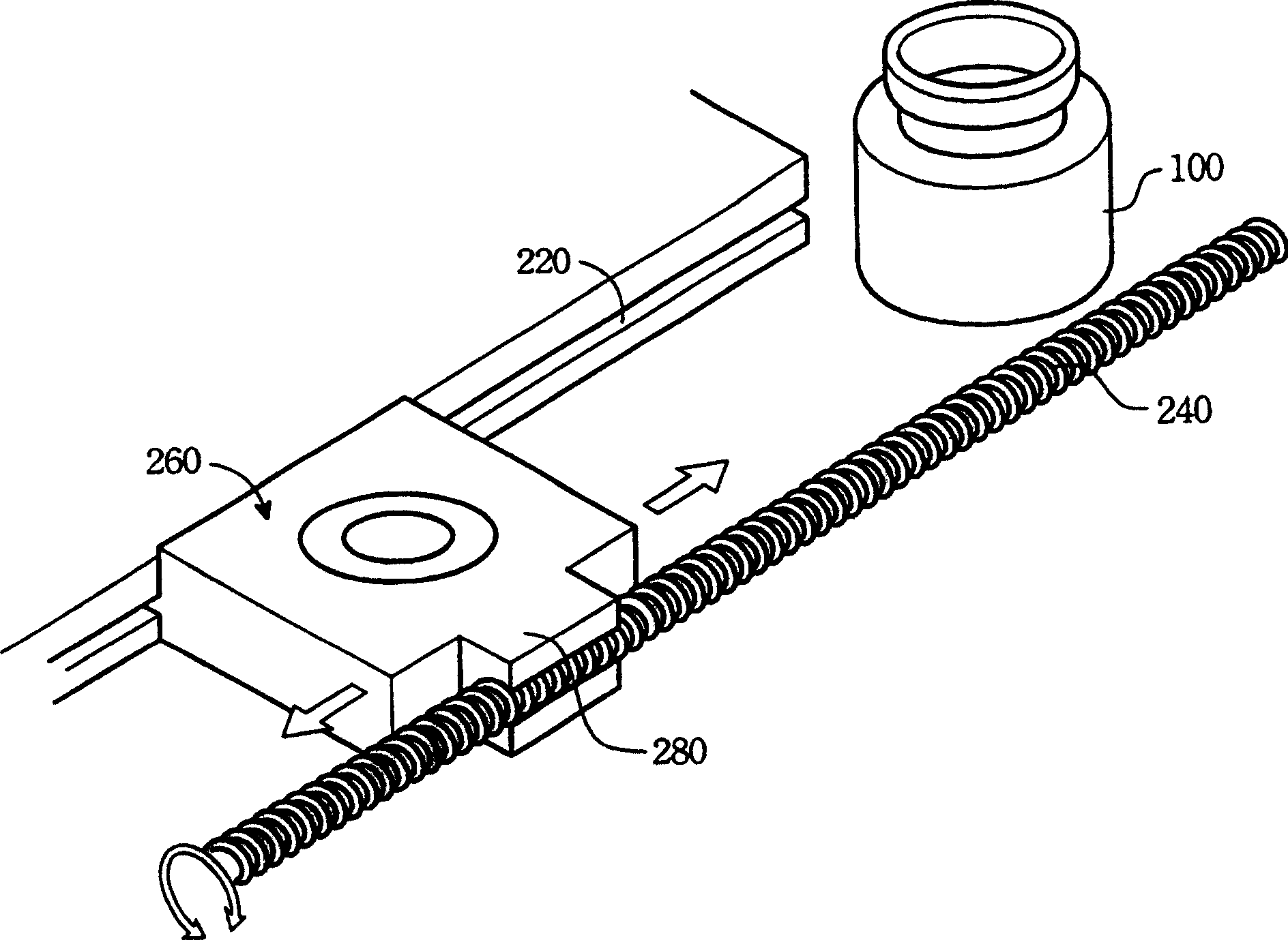
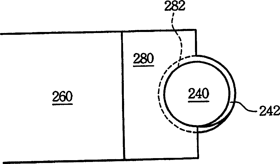
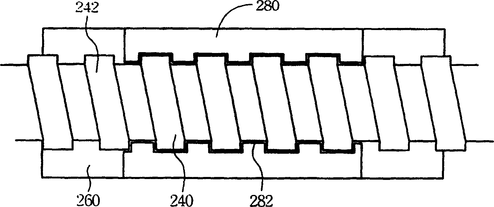
[0023] Please refer to Figure 4 Shown is a schematic diagram of a preferred embodiment of the automatic oiling device 400 of the present invention. The automatic oiling device 400 includes a screw base 420 , a movable driving part 440 and an oil supply 460 . Wherein, the screw seat 420 is used to carry and position the screw 240 to be oiled, and the movable driving part 440 is located above the screw seat 420 to engage with the screw 240 . The oil supply 460 is fixed on the driving part 440 and has an oil injection nozzle 462 extending to the inside of the driving part. When the driving part 440 engages downwardly on the screw rod 240 , the grease nozzle 462 is also aligned with the thread of the screw rod 240 . Subsequently, the driving part moves linearly along the axial direction of the screw rod 240 , drives the screw rod 240 to rotate at the same time, and makes the oil injection nozzle 462 move along the thread of the screw rod 240 to inject oil therein.

[0024] Als...


PUM


Abstract

This invention relates to automatic oil device, which comprise one screw socket, one moving driver and one oil supplier, wherein, the screw socket is to support and position the oil screw lever; the moving driver is located above the screw lever socket to mesh the screw lever; the supplier is fixed on the driver with one oil filling mouth to the screw thread; the driver is meshed to the screw lever moving along the axis direction with screw lever and to make the mouth moving along the screw thread.

Description

technical field [0001] The invention relates to an automatic oiling device for a screw, in particular to an automatic oiling device for a screw of a disc drive. Background technique [0002] With the rapid development of personal computers, the market for computer peripheral products has also grown rapidly. Computer peripheral products such as hard disk drives, CD-ROM drives, scanners, and printers have all become necessary tools for modern offices. Among these computer peripheral products, an optical disc drive is a commonly used storage medium at present. In addition to providing a large storage capacity, the optical disc drive also provides a variety of storage data formats and the benefits of long-term data preservation. Especially with the development of a new generation of digital video discs (Digital Versatile Disc, DVD), providing up to 17GB of storage capacity and higher quality image and audio output, so that the application of the optical disc drive is more exten...

Claims


Application Information

Patent Timeline
IPC IPC(8): G11B7/12G11B33/14
Inventor 林永隆
Owner PEGATRON
Why Eureka
Try Eureka