Needle with transfer spring

A technology of loop transfer and loop formation, which is applied in knitting, weft knitting, textile and papermaking, etc., to ensure smooth running, reduce safety distance, and reduce lateral deviation

Inactive Publication Date: 2007-03-14
GROZ BECKERT KG
View PDF10 Cites 2 Cited by
  • Summary
  • Abstract
  • Description
  • Claims
  • Application Information

AI Technical Summary

Problems solved by technology

If the transfer spring is loose

Method used


Image

  • Needle with transfer spring
  • Needle with transfer spring
  • Needle with transfer spring

Examples


Embodiment Construction

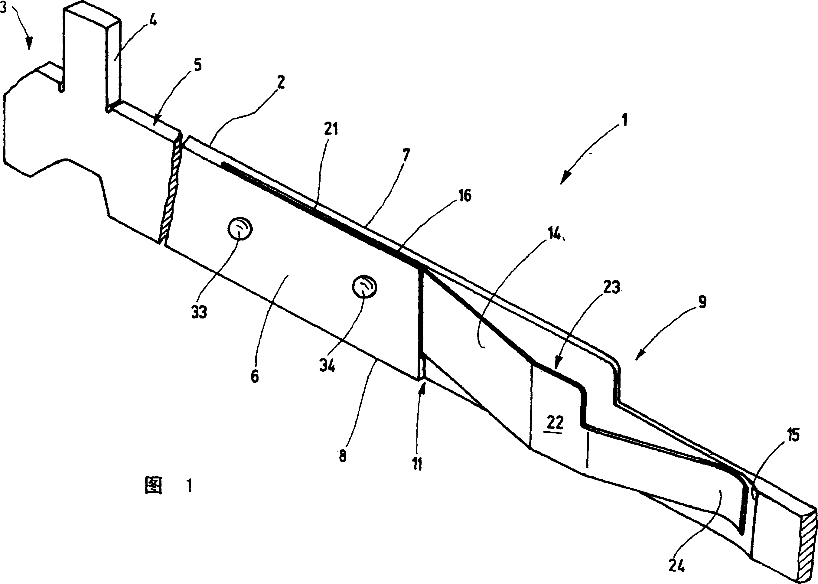
[0026] FIG. 1 shows a detail of a needle 1 for a knitting machine in the form of a transfer needle. The needle has a needle body 2 which supports a hook, not otherwise shown, at an end cut off in FIG. 1 . Arranged at its other end 3 or at another suitable location is a needle foot 4 which protrudes from the narrow side 5 of the needle body 2 , which is substantially rectangular in cross section. The narrow side 5 forms the upper side of the needle. On both sides of the narrow side 5 , the needle body 2 has two flat sides 6 , 7 which form substantially flat, closed surfaces aligned parallel to one another. On the underside of the needle body 2 there is a further narrow side 8 parallel to the narrow side 5 which forms the back of the needle.

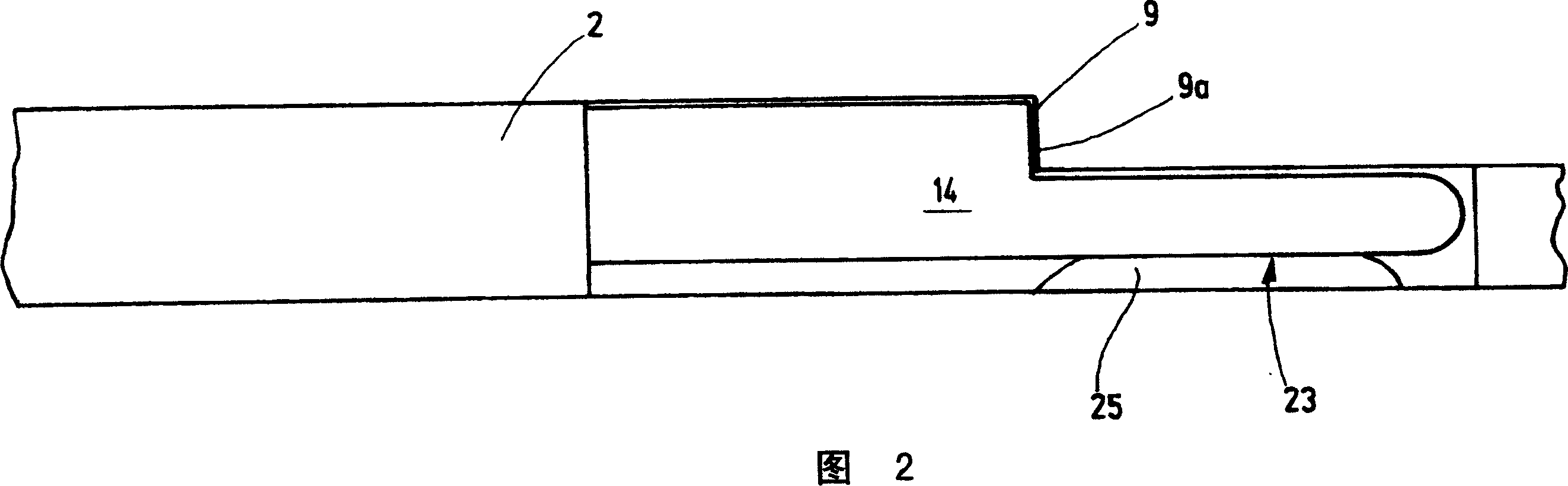
[0027] The measured height of the needle body 2 between the narrow sides 5 , 8 can vary along the length of the needle body 2 . For example, as shown in FIG. 1, a step 9 can be provided where the height decreases towards a not shown hoo...


PUM


Abstract

The stitch transfer needle (1), for a knitter, has a needle body (2) with two flat sides (6,7) bonded together by narrow sides (5,8) at the top and the side. A narrow slit (16) opens at one of the narrow sides, extending in the needle body parallel or at an acute angle to the flat sides. A rectangular mounting section (21) of the stitch transfer spring (14) is held in the slit in a positive fit and/or a force fit and/or a fused fit.

Description

technical field [0001] The invention relates to a needle for a knitting textile machine, in particular to a knitting transfer needle. Background technique [0002] For loop-forming textile machines, loop-transfer needles are known which are arranged in such a way as to transfer a built-up loop to another needle. [0003] Such a transfer needle is known from DE 199 05 668 A1. The needle has a body with an elongated shaft defining a back and a side. The needle bar is divided into a high section and a low section. On one of its sides, the high section has a recess for receiving a rectangular fastening section of a transfer spring. The fastening section is located in a bag, where it rests with its upper edge and its lower edge on the bag flange. The depth of the pocket is slightly greater than the thickness of the fastening section of the transfer needle. In order to secure the transfer needle in the pocket, a raised and lowered position can be provided. Furthermore, from ...

Claims


Application Information

Patent Timeline
IPC IPC(8): D04B35/04D04B15/02D04B35/02
CPCD04B35/02
Inventor R·罗斯
Owner GROZ BECKERT KG
Why Eureka
Try Eureka