A circular weft knitting machine

A weft knitting machine and circular technology, which is applied in the field of knitting circular weft knitting machines, can solve the problems of reducing the yarn transmission rate, reducing the speed of the yarn feeder, and reducing production efficiency, so as to increase tension, reduce workload, and improve The effect of production efficiency

Active Publication Date: 2020-09-08
绍兴皂树纺织科技有限公司
View PDF1 Cites 0 Cited by
  • Summary
  • Abstract
  • Description
  • Claims
  • Application Information

AI Technical Summary

Problems solved by technology

[0004] The above-mentioned existing technical solutions have the following defects: because the endless synchronous belt realizes the cooperation between the protrusion and the concave hole through its own tension, it is easy to deform when the endless synchronous belt is used for a long time, so that the annular synchronous belt is deformed, and the annular synchronous belt and the Slipping is prone to occur between the transmission wheels of the yarn feeder, thereby reducing the speed of the yarn feeder and the transmission rate of the yarn, thereby reducing production efficiency

Method used


Image

  • A circular weft knitting machine
  • A circular weft knitting machine
  • A circular weft knitting machine

Examples


Embodiment Construction

[0037] The present invention will be described in further detail below in conjunction with the accompanying drawings.

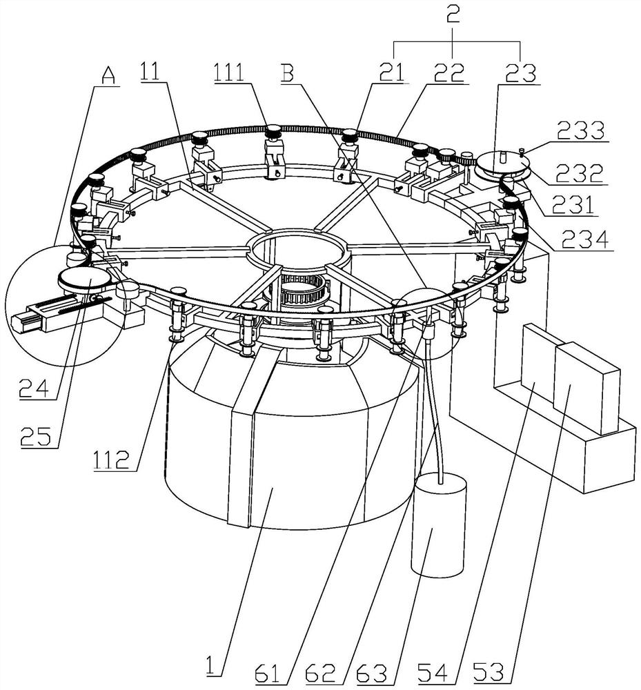
[0038] refer to figure 1 , is a kind of knitting circular weft knitting machine disclosed by the present invention, comprising a creel 11, a plurality of yarn feeders 111 distributed around the circumference of the creel 11, a yarn feeder 112 arranged on the yarn feeder 111, and The driving mechanism 2 arranged on the frame 1 drives the yarn delivery wheel 112 to run. The creel 11 is in the shape of a circular frame, and the frame 1 supporting the creel 11 is placed on the ground, and the creel 11 is fixed on the top of the frame 1 by screws. The yarn bobbin of thread, the yarn on the yarn bobbin enters in the weft knitting machine after being transferred by the yarn feeder 111 for weaving.

[0039] The yarn feeders 111 are distributed at equal angular intervals along the circumference of the yarn frame 11, and the yarn feeder 112 is in the shape of a cylin...


PUM


Abstract

The invention relates to a circular weft knitting machine, and relates to the technical field of textile processing devices. The circular weft knitting machine comprises a creel, a plurality of yarn conveying devices, yarn conveying wheels and a driving mechanism, the yarn conveying devices are peripherally distributed in a surrounded manner, the yarn conveying wheels are rotatably arranged on theyarn conveying devices, the driving mechanism is arranged on the creel, the driving mechanism comprises a plurality of driving wheels, a synchronous belt, a power wheel, a driving motor, a sliding seat, an adjusting wheel, a driving component, the driving wheels are coaxially fixed with the yarn conveying wheels, the synchronous belt surrounds the driving wheels and are connected with the drivingwheels in an engaged manner, the power wheel is rotatably arranged on the creel and is engaged with the synchronous belt, the driving motor is arranged on the creel and drives the driving wheels to rotate, the sliding seat is slidably arranged on the creel along the direction close to or far away from the yarn conveying wheels, the adjusting wheel is rotatably arranged on the sliding seat and connected with the synchronous belt in an engaged manner, the driving component drives the sliding seat to slide, and yarns are led out from a yarn barrel and wound on the peripheral side walls of the yarn conveying wheels. The weft knitting machine has the advantages that the tension of the synchronous belt is adjusted, and sliding of the synchronous belt and driving wheels is avoided, so that production efficiency is improved.

Description

technical field [0001] The invention relates to the technical field of textile processing equipment, in particular to a circular weft knitting machine for knitting. Background technique [0002] At present, the fabric weaving methods commonly used in the textile industry include warp knitting and weft knitting. Weft knitting is to form loops sequentially with knitting needles along the transverse direction of the fabric with one or several yarns, and interlock each other in the longitudinal direction. Weft-knitted fabrics can be divided into single-sided and double-sided. Weft knitting: The weaving method in which the yarn running in the weft direction is bent up and down segment by segment to form a coil, which is sequentially inserted into the coil formed by the previous yarn, and looped to form a cloth. The weaving mode that adopts weft knitting mainly contains circular weft knitting machine in existing textile processing equipment. Because the knitting circular weft kn...

Claims


Application Information

Patent Timeline
Patent Type & Authority Patents(China)
IPC IPC(8): D04B15/38D04B15/94D04B15/99
CPCD04B15/38D04B15/94D04B15/99
Inventor 黄承君
Owner 绍兴皂树纺织科技有限公司
Why Eureka
Try Eureka