Supercharge Your Innovation With Domain-Expert AI Agents!

Optical fiber cable for air-blown installation

A fiber optic cable and air blowing technology, applied in light guides, optics, optical components, etc., can solve problems such as poor flexibility and difficult laying of optical cables into curved or curved pipelines

Inactive Publication Date: 2007-03-14
SAMSUNG ELECTRONICS CO LTD
View PDF4 Cites 0 Cited by
  • Summary
  • Abstract
  • Description
  • Claims
  • Application Information

AI Technical Summary

Problems solved by technology

[0013] However, due to the poor flexibility caused by the tension element, the fiber optic cable is not easy to lay in curved pipelines or curved pipelines

Method used


Image

  • Optical fiber cable for air-blown installation
  • Optical fiber cable for air-blown installation
  • Optical fiber cable for air-blown installation

Examples


Embodiment Construction

[0025] An optical cable for air blowing laying according to a preferred embodiment of the present invention will be described below with reference to the accompanying drawings. In the following description of the present invention, detailed descriptions of known functions and configurations included herein will be omitted for clarity.

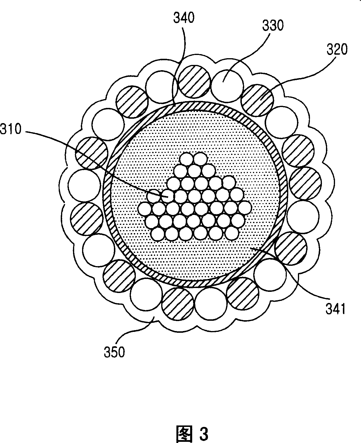
[0026] Fig. 3 shows the construction of a fiber optic cable with a single tube structure, which features a plurality of optical fibers, according to a preferred embodiment of the present invention. The optical cable includes a plurality of optical fibers 310 as a medium for transmitting optical signals; a tube 340 binding the optical fibers 310; a plurality of line fillers 330 surrounding the outer circumference of the tube 340; tension member 320; and outer sheath 350.

[0027] The optical fiber 310 serves as a medium for transmitting optical signals, and is installed inside the tube 340 . The empty space between the tube 340 and the optical...


PUM


Abstract

An optical fiber cable for air-blown installation includes optical fibers acting as a medium for transmitting optical signals; a tube binding the optical fibers; string fillers surrounding the outer periphery of the tube at a predetermined spacing, tensile members positioned between the string fillers to surround the outer periphery of the tube for improving the tensile force of the optical fiber cable; and an outer sheath formed in a flexuous shape to surround the outer circumferences of the string fillers and the tensile members.

Description

technical field [0001] The present invention relates to optical cables, and in particular to optical cables for air blown laying between telephone exchanges and subscriber networks. Background technique [0002] Optical cables are used as a medium for transmitting optical signals through optical fibers. It includes an optical fiber, a tension element, a waterproof element, and an outer jacket to protect and enhance the physical properties of the stranded optical fiber. Optical fibers are glass wires made from materials such as silica, which is mainly derived from quartz, and are easy to handle and lay due to their hair-thin diameter. An optical fiber includes a core for transmitting light therein, a cladding for confining the propagation of light within the core, and a jacket for surrounding the cladding. [0003] Fiber optics have many advantages over coaxial cables, but the problem is that fiber optics are susceptible to physical and environmental factors. Therefore, op...

Claims


Application Information

Patent Timeline
Patent Type & Authority Patents(China)
IPC IPC(8): G02B6/44G02B6/00
CPCG02B6/4438G02B6/4435G02B6/44
Inventor 文承铉
Owner SAMSUNG ELECTRONICS CO LTD
Features
  • R&D
  • Intellectual Property
  • Life Sciences
  • Materials
  • Tech Scout
  • Unparalleled Data Quality
  • Higher Quality Content
  • 60% Fewer Hallucinations
Learn More