
Stack coil device and manufacturing method thereof

A coil device, non-magnetic technology, used in coil manufacturing, coil, inductor/transformer/magnet manufacturing, etc., can solve problems such as electromagnetic coupling and improvement of impedance characteristics.

Inactive Publication Date: 2007-03-28
CERATECH
View PDF2 Cites 0 Cited by
  • Summary
  • Abstract
  • Description
  • Claims
  • Application Information

AI Technical Summary

Problems solved by technology

Therefore, leakage magnetic flux is generated, so the improvement of electromagnetic coupling and impedance characteristics is limited

Method used


Image

  • Stack coil device and manufacturing method thereof
  • Stack coil device and manufacturing method thereof
  • Stack coil device and manufacturing method thereof

Examples


Embodiment Construction

[0040] Reference will now be made in detail to preferred embodiments of the present invention, specific examples of which are shown in the accompanying drawings.

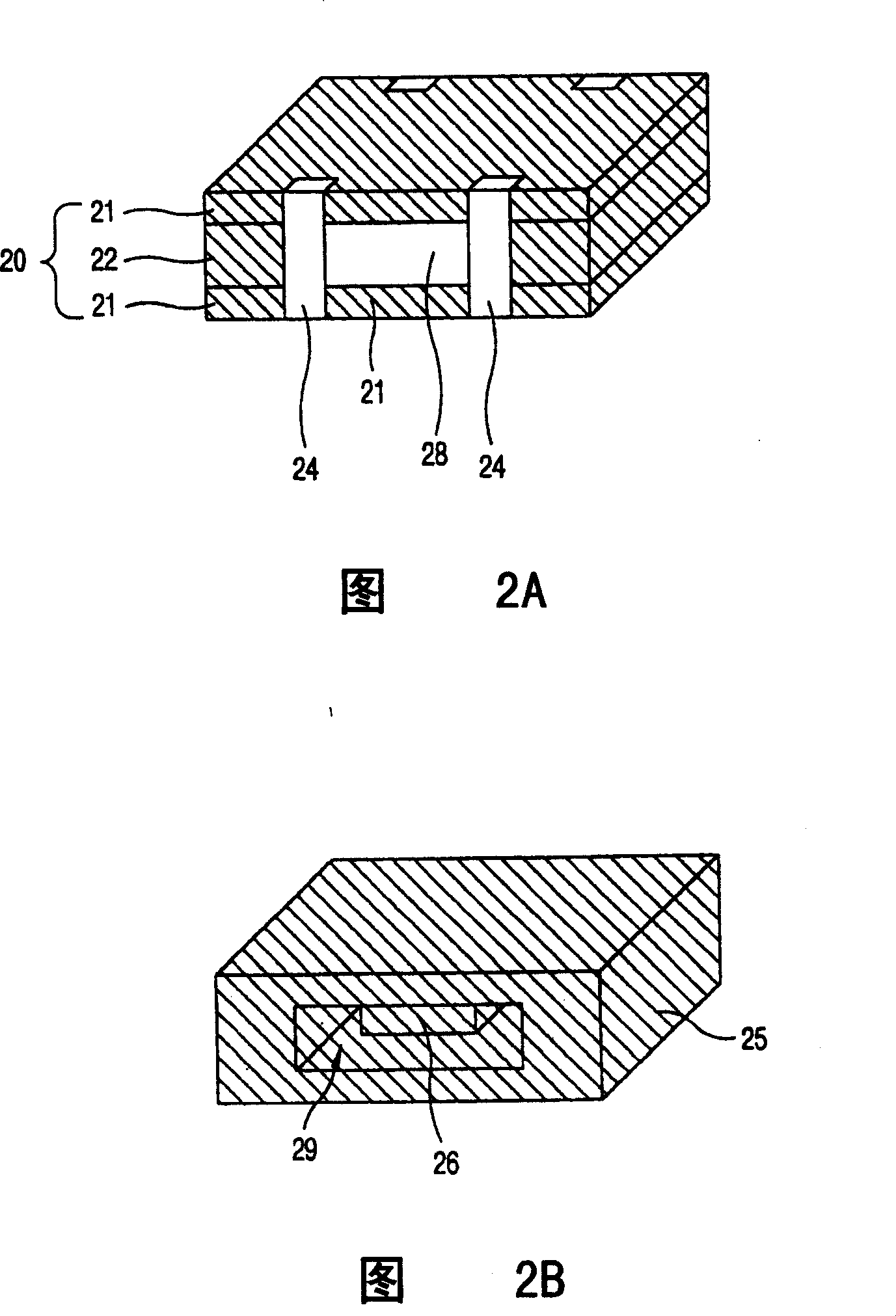
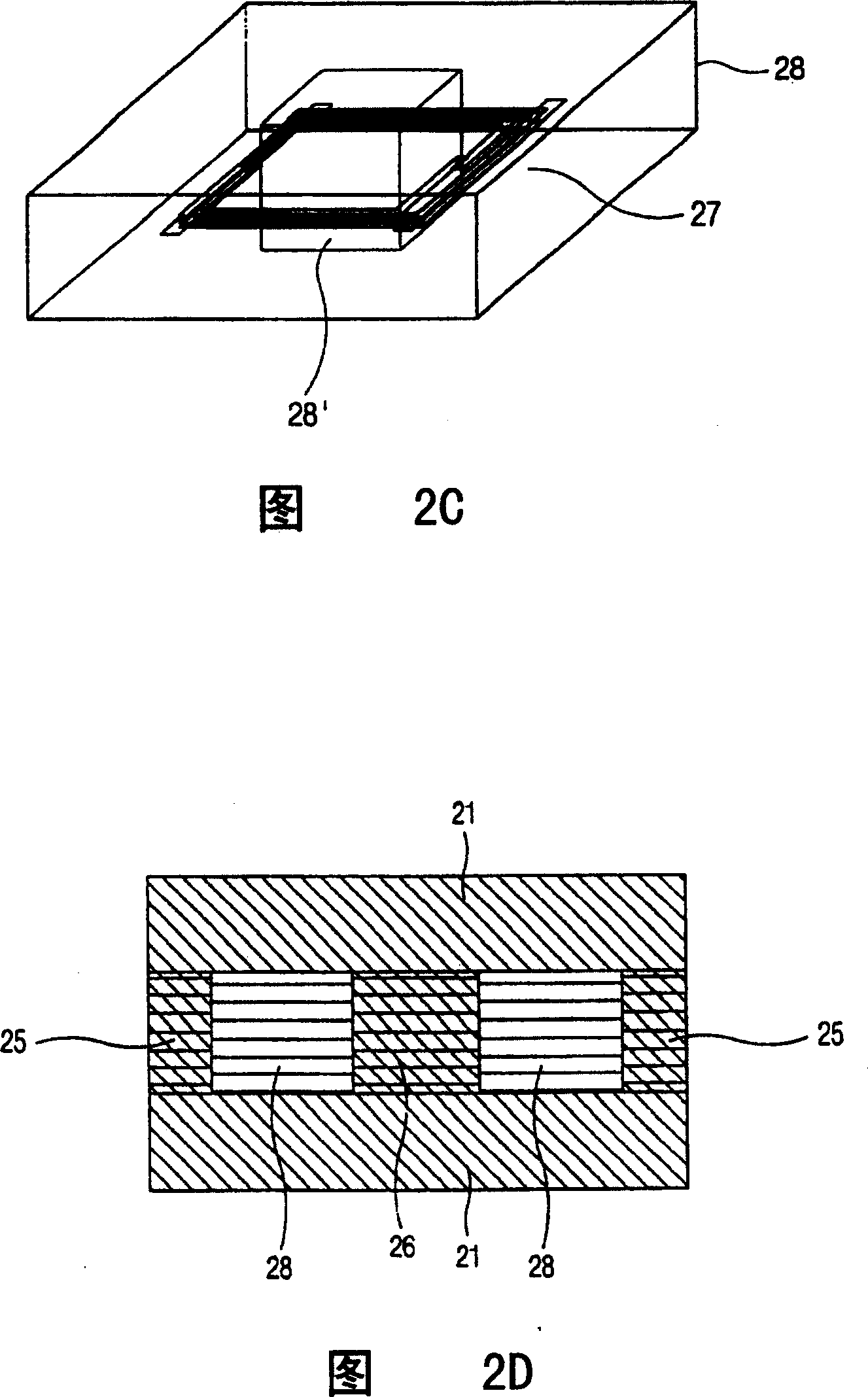
[0041] 2A-2D are perspective views illustrating the appearance and internal structure of the coil device of the present invention.

[0042] As shown in FIG. 2A , cover layers are formed on the upper and lower surfaces of the hexahedron-shaped coil device, and external electrode terminals 24 are formed on the outer peripheral surface of the stacked main body 20 . Also, a magnetic layer 22 and a nonmagnetic layer 28 are provided between the cover layers 21 .

[0043] Figure 2B shows only the magnetic inner layer in the coil arrangement, where the magnetic circuit can be shown. It can be seen here that in FIG. 2A , the central magnetic layer 26 is not shown because it is placed at the center of the non-magnetic electrode layer. The inner space 29 formed by the central magnetic layer 26 and the side magnetic layers 25...


PUM


Abstract

A stacked coil device comprising: an inner electrode layer formed of at least two layers and having a non-magnetic electrode layer and an inner magnetic layer as one unit, the non-magnetic electrode layer provided with an opening at a center thereof and provided with an electrode pattern on at least one surface of an upper surface and a lower surface thereof and the inner magnetic layer positioned at the center opening and a lateral surface of the non-magnetic electrode layer; a cover layer in contact with both surfaces of the inner electrode layer; and an external electrode terminal partially and electrically connected to the electrode pattern.

Description

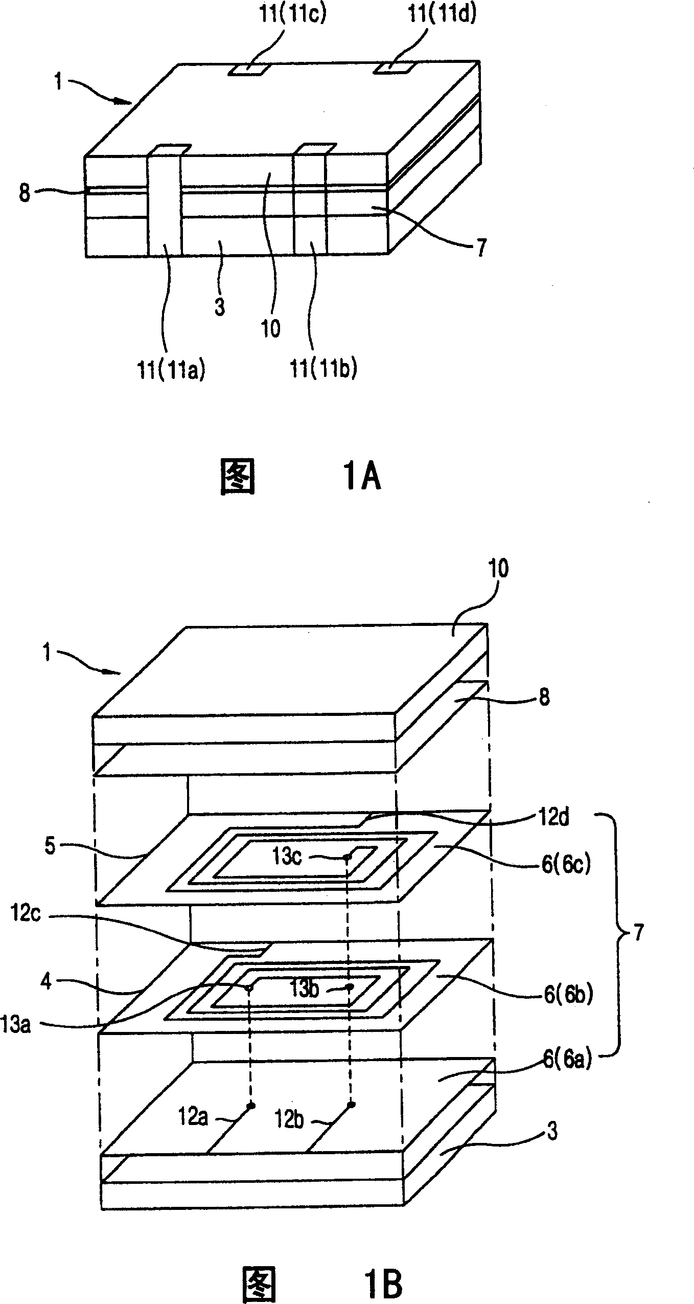
technical field [0001] The present invention relates to stacked coil arrangements, and more particularly to coil arrangements that can be used as transformers, common mode choke coils, and the like. Background technique [0002] Generally, in order to enhance the electrical characteristics of a coil device such as a common mode choke coil or a transformer, it is necessary to increase the electromagnetic coupling between the first coil and the second coil. To increase the electromagnetic coupling between the first and second coils, the interval between the first and second coils must be small, or the magnetic circuit formed must not generate leakage flux. [0003] FIG. 1A is a perspective view showing a common mode choke coil including a prior art coil device, and FIG. 1B is an exploded view of the common mode choke coil of FIG. 1A . [0004] As shown in FIG. 1A , the common mode choke coil 1 includes a stack body 7 formed on the top of the first magnetic substrate 3 , a sec...

Claims


Application Information

Patent Timeline
Patent Type & Authority Patents(China)
IPC IPC(8): H01F27/28H01F41/04H01F17/00H01F5/00H01F27/245H01F37/00
CPCH01F2017/0093H01F27/2804H01F17/0013H01F41/046Y10T29/4902H01F27/245
Inventor 洪淳奎崔明姬张相恩
Owner CERATECH
Learn More