Filtering circuit with slot line resonators
a filtering circuit and slot line technology, applied in waveguides, basic electric elements, waveguide type devices, etc., can solve the problems of high cost, bulky, and high processing cost, and achieve the effect of reducing transmission losses during filtering
- Summary
- Abstract
- Description
- Claims
- Application Information
AI Technical Summary
Benefits of technology
Problems solved by technology
Method used
Image
Examples
Embodiment Construction
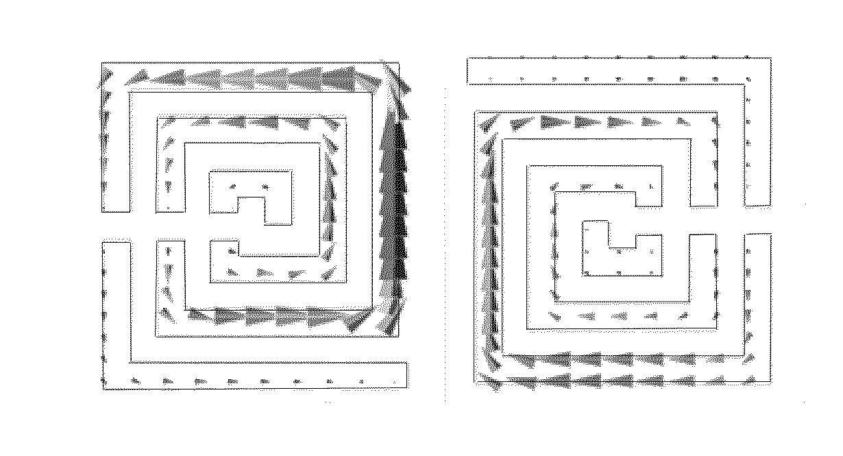
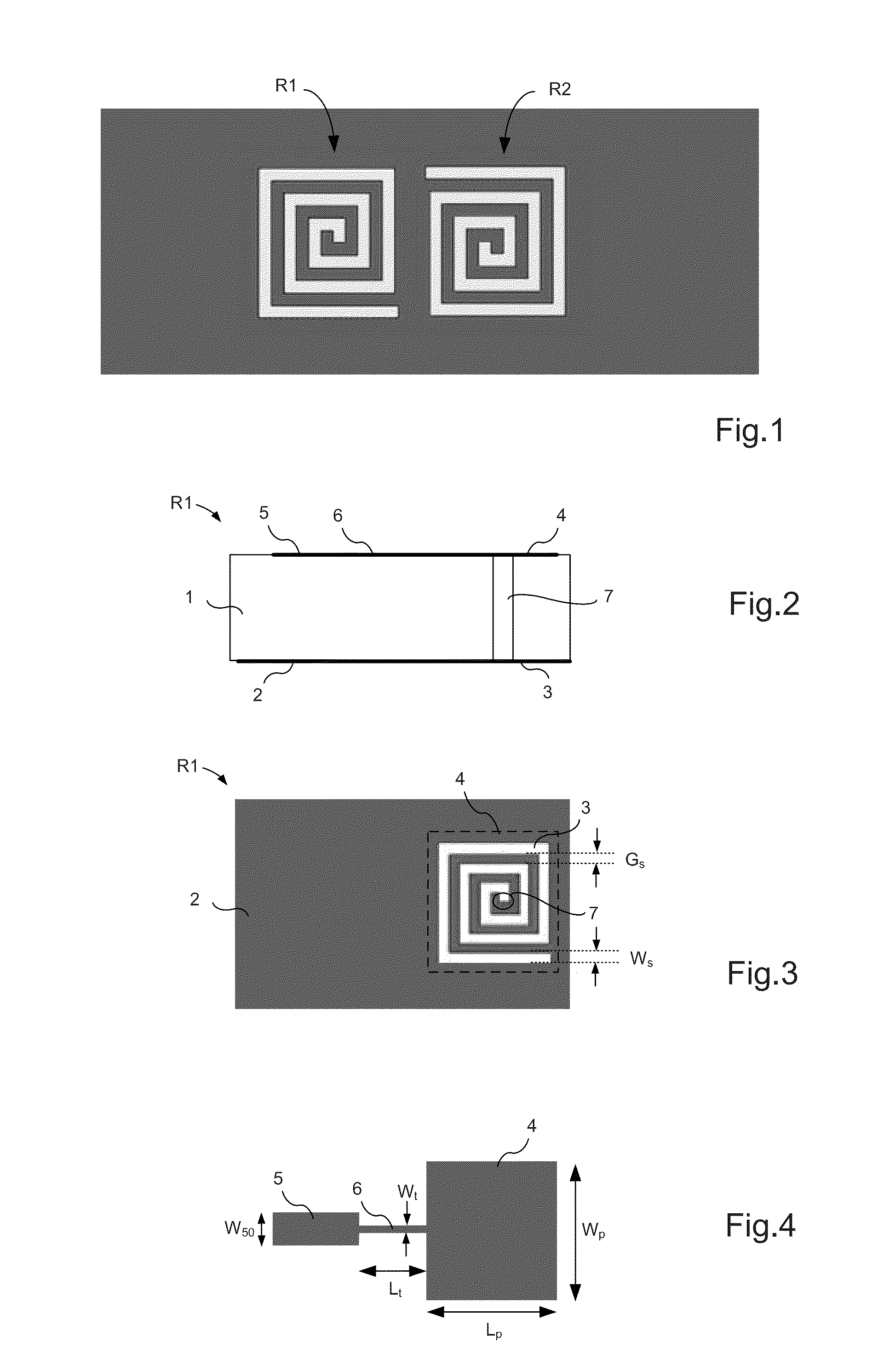
[0050]FIG. 1 shows a simplified diagram of two coupled resonators, R1 and R2, that are arranged side by side to form a filter. Each of the two resonators is a spiral slot line resonator as shown diagrammatically in FIGS. 2 to 4. These figures show more particularly the resonator R1. Such a resonator is for example described in the French patent application no. 1450769.
[0051]The resonator is realised on a dielectric substrate featuring on each of its faces a conductive layer. FIGS. 2 to 4 respectively show a cross-section view of the substrate on which the resonator is realised, a view of the lower face and a view of the upper face of the substrate.
[0052]More specifically, a dielectric substrate 1 is equipped on one of its faces with a conductive layer 2 wherein a slot line has been etched in a spiral pattern 3. This slot line has a width Ws and a length L which is a function of the operating frequency of the resonator.
[0053]On the face of the substrate opposite the conductive layer ...
PUM
 Abstract
Description
Claims
Application Information
 - R&D
- Intellectual Property
- Life Sciences
- Materials
- Tech Scout
- Unparalleled Data Quality
- Higher Quality Content
- 60% Fewer Hallucinations
Browse by: Latest US Patents, China's latest patents, Technical Efficacy Thesaurus, Application Domain, Technology Topic, Popular Technical Reports.
© 2025 PatSnap. All rights reserved.Legal|Privacy policy|Modern Slavery Act Transparency Statement|Sitemap|About US| Contact US: help@patsnap.com


