
Coupling structure of optical fiber and light wave guide

A coupling structure and optical waveguide technology, applied in the field of optical coupling structure, can solve the problems of light loss, increase of light propagation loss, and influence of beam luminous flux, etc.

Inactive Publication Date: 2007-05-23
IND TECH RES INST
View PDF3 Cites 0 Cited by
  • Summary
  • Abstract
  • Description
  • Claims
  • Application Information

AI Technical Summary

Problems solved by technology

However, when the light beam enters the receiving optical waveguide from the end face of the optical fiber and enters the output optical fiber end face from the optical waveguide, the incident light is perpendicular to the truncated end faces of the two, which will cause stray light to reflect on the incident light and the truncated end face, and enter the receiving optical waveguide to cause Non-coherent resonance, the alignment coupling between the optical waveguide and the end face of the fiber will cause optical loss, increase the loss of light propagation, and then affect the light flux of the beam entering and outputting the optical waveguide

Method used


Image

  • Coupling structure of optical fiber and light wave guide
  • Coupling structure of optical fiber and light wave guide

Examples


Embodiment Construction

[0022] In order to have a further understanding of the purpose of the present invention, structural features and functions thereof, the accompanying drawings are described in detail as follows:

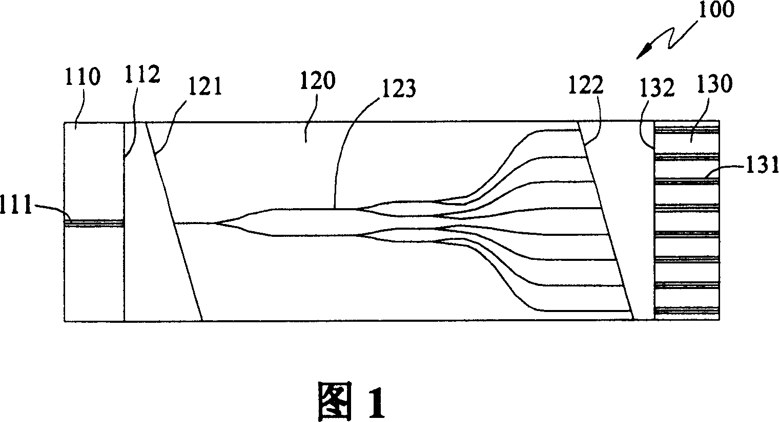
[0023] The present invention takes the passive optical splitter made by the optical waveguide as an embodiment, and manufactures the optical path and coupling structure constructed by the passive optical splitter and the optical fiber on the substrate, and can be applied to the optical fiber communication system and other optical systems.

[0024] Please refer to FIG. 1 , which is a schematic diagram of a first embodiment of the present invention. The light input region 110 , the light waveguide region 120 and the light output region 130 are formed on the silicon substrate 100 . The light input area 110 has a first auxiliary alignment groove 111 to accommodate an input optical fiber (not shown) to transmit the input light to the optical waveguide area 120, the light input area 110 has...


PUM


Abstract

The present invention relates to a coupling structure of optical fibre and optical waveguide, and is used for coupling optical fiber and transmission beam of optical waveguide zone. On one base plate the optical waveguide zone and more than one auxiliary aligning channel for placing optical fiber are made. Besides, said invention also provides the concrete structure of said optical waveguide zone and its concrete making method and steps.

Description

technical field [0001] The invention relates to an optical coupling structure of an optical path system, in particular to a coupling structure of an optical fiber and an optical waveguide. Background technique [0002] Optical waveguide components have the advantages of good stability, mass production, integration, high sensitivity, and immunity to electromagnetic interference, so they can be used in various environments. Planar Lightwave Circuits (PLCs) technology is a technology that uses semiconductor technology to fabricate many optical waveguide channels on a plane to have the functions of light splitting, light combining and optical switching (optical switch), and is dedicated to the separation of components. Integrated into a complete platform to reduce overall module size, reduce system complexity, reduce signal loss, increase component reliability and yield, etc. [0003] The planar optical waveguide uses a silicon chip as the substrate, and then deposits three lay...

Claims


Application Information

Patent Timeline
Patent Type & Authority Patents(China)
IPC IPC(8): G02B6/24
Inventor 杨建成刘文俊萧志诚
Owner IND TECH RES INST
Learn More