Base station device, communication terminal and transmission power control method
A technology for transmission power control and communication terminals, which is applied to communication between multiple stations, power management, wireless communication, etc., and can solve problems such as signal quality degradation and other user interference
- Summary
- Abstract
- Description
- Claims
- Application Information
AI Technical Summary
Problems solved by technology
Method used
Image
Examples
Embodiment 1
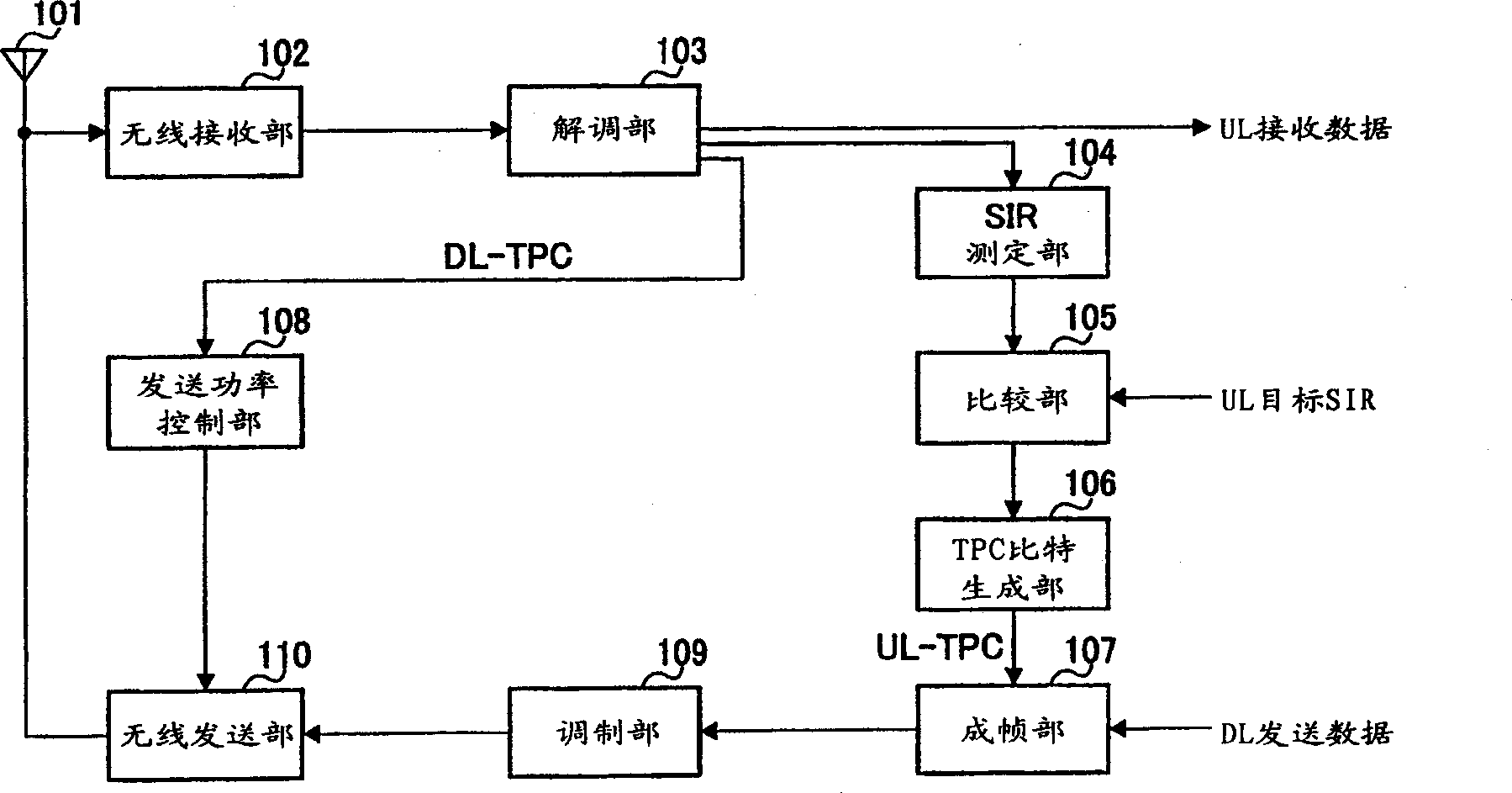
[0030] figure 1 It is a block diagram showing the structure of the base station apparatus according to Embodiment 1 of the present invention. exist figure 1 Among them, the signal from the communication terminal device received via the antenna 101 is subjected to predetermined processing such as frequency conversion by the wireless receiving unit 102 . The reception signal after the above-mentioned predetermined processing is demodulated by the demodulation unit 103 . The demodulated signal is obtained as UL reception data and sent to the SIR measurement unit 104 .
[0031] In the SIR measurement unit 104, SIR is measured from the demodulated signal. The measured SIR is compared with the UL target SIR in the comparison unit 105 . Specifically, subtraction processing is performed between the measured SIR and the UL target SIR. That is, in the comparison unit 105 , the extent to which the measured SIR deviates from the target (ideal) SIR is determined.
[0032] The subtrac...
Embodiment 2
[0064]In this embodiment, a case will be described in which a known signal is transmitted from a base station device to a communication terminal device using a time slot before resumption of transmission, and transmission power control information obtained from the quality of the known signal is transmitted from the communication terminal device. The base station apparatus performs transmission power control capable of compensating for a difference between downlink signal quality and downlink desired quality based on the transmission power control information.
[0065] The base station apparatus and communication terminal apparatus in this embodiment have the same configuration as that of Embodiment 1, and therefore description thereof will be omitted.
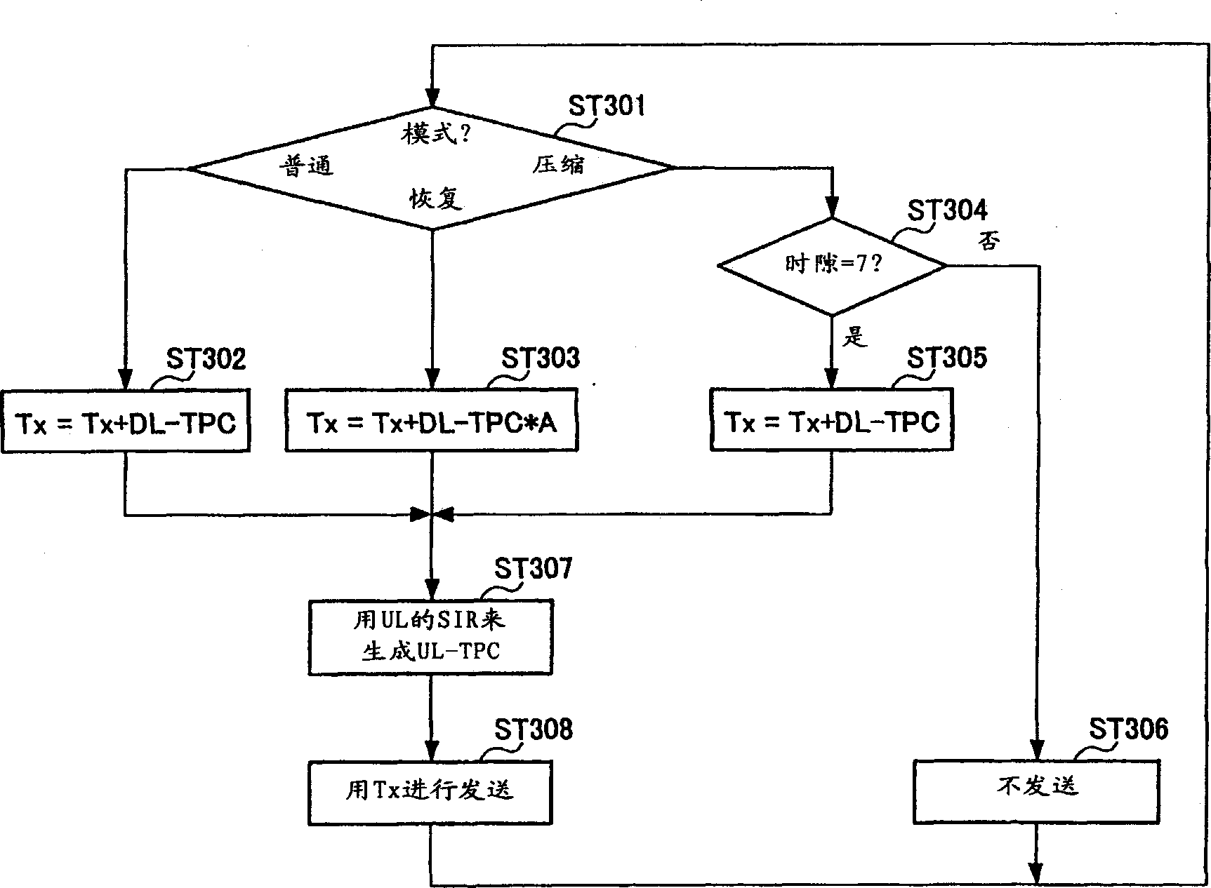
[0066] The transmission power control method performed by the base station apparatus and the communication terminal apparatus of this embodiment will be described below. Here, a case will be described in which the period in wh...
Embodiment 3
[0083] In this embodiment, the following case is described: using a channel common to all users, such as a known signal of a common pilot channel, and a known signal of an individual physical channel in a compressed mode, such as a pilot signal, these known signals The transmission power ratio of the known signal is used to perform transmission power control capable of compensating for the difference between the downlink signal quality and the downlink desired quality based on the transmission power control information.
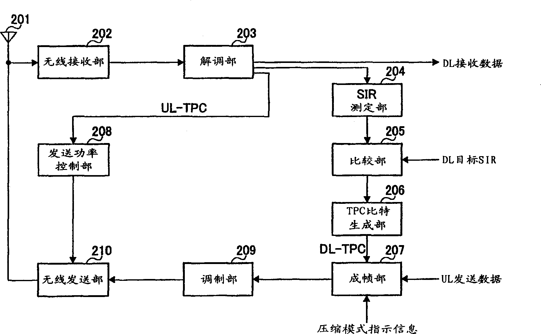
[0084] The base station apparatus in this embodiment has the same configuration as that in Embodiment 1, and therefore its description is omitted. use Figure 10 The configuration of the communication terminal device of this embodiment will be described.
[0085] exist Figure 10 Among them, the signal from the base station apparatus received via the antenna 1001 is subjected to predetermined processing such as frequency conversion by the radio receiving un...
PUM
 Abstract
Description
Claims
Application Information
 - R&D
- Intellectual Property
- Life Sciences
- Materials
- Tech Scout
- Unparalleled Data Quality
- Higher Quality Content
- 60% Fewer Hallucinations
Browse by: Latest US Patents, China's latest patents, Technical Efficacy Thesaurus, Application Domain, Technology Topic, Popular Technical Reports.
© 2025 PatSnap. All rights reserved.Legal|Privacy policy|Modern Slavery Act Transparency Statement|Sitemap|About US| Contact US: help@patsnap.com


