
Synchronous rotary compressor

A compressor and rotary technology, applied in the field of compressors, can solve the problems of high machining accuracy, short life of wearing parts, poor reliability, etc., and achieve the effects of reducing flow resistance loss, smooth machine operation, and reducing friction and wear.

Active Publication Date: 2007-06-27
DAFENG FENGTAI FLUID MACHINERY TECHNOLOGY CO LTD
View PDF7 Cites 5 Cited by
  • Summary
  • Abstract
  • Description
  • Claims
  • Application Information

AI Technical Summary

Problems solved by technology

In addition, the reciprocating compressor is difficult to balance due to the inertial force of the movement, the vibration is large, the life of the wearing parts is short and the reliability is poor.
Due to the high processing precision and complicated process of the scroll compressor, the cost is high

Method used


Image

  • Synchronous rotary compressor

Examples


Embodiment Construction

[0008] The structural principle and working principle of the present invention will be further described in detail below in conjunction with the accompanying drawings.

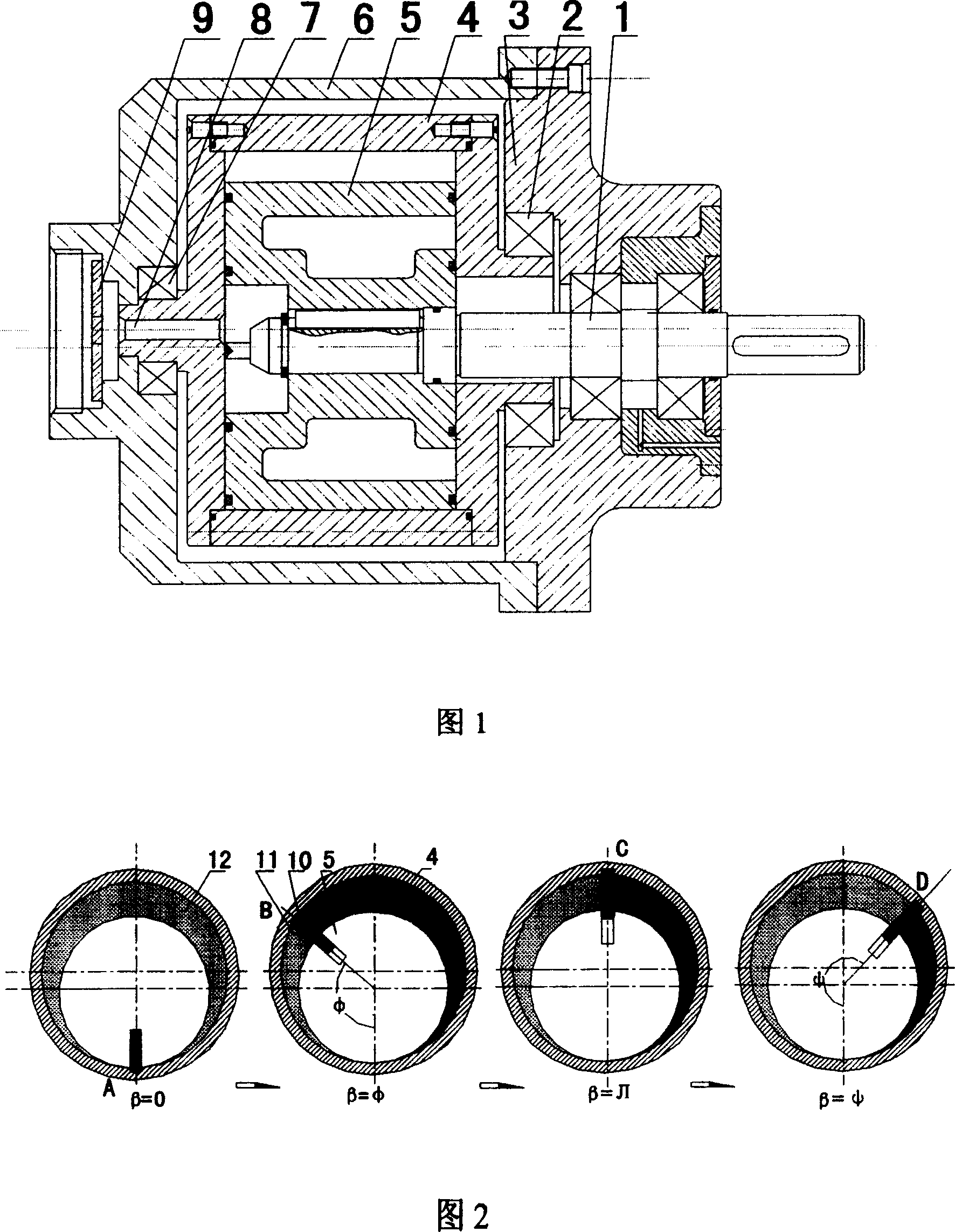
[0009] Referring to Fig. 1, the present invention includes a cylinder 4 and a rotor 5 set in the cylinder 4 and mounted on the drive shaft 1, and a slide plate 10 that can be embedded in the cylinder 4 is also provided on the rotor 5, and the cylinder 4 that can rotate with the rotor 5 passes through the machine. The frame bearing 7 is installed on the fixed frame 6, and the fixed frame 6 is also provided with an exhaust valve 9 communicating with the exhaust hole 8 of the cylinder, and the cylinder 4 is concentric with the fixed frame 6, and is not on the same axis as the rotor 5. The fixed frame 6 on the center is installed on the eccentric seat 3 through the support bearing 2. When the drive shaft 1 rotates, it drives the rotor 5 to make a complete rotary motion, and the slide plate 10 is embedded in the cy...


PUM


Abstract

The revolve compressor is composed of fixed frame and eccentricity seat connected with the fixed frame. In the air cavity comprised by the frame and eccentricity seat, the rotor sleeved on the driving shaft is fixed, the sliding bar installed on the rotor can be embedded to the cylinder. The cylinder is fixed in the air cavity, through the frame bearing and support bearing; the shaft of the cylinder and rotor and not in the same axis line. As the driving axis rotate, the rotor make revolve moment, the sliding plate embedded to the cylinder due to the effect of centrifugal force which pushes the cylinder make the same revolve movement.

Description

technical field [0001] The invention belongs to the field of compressors, in particular to a synchronous rotary compressor. Background technique [0002] Currently used compressors include reciprocating compressors, rolling rotor compressors, and sliding vane compressors. Due to the inertial force that is difficult to balance, the reciprocating compressor has large vibration, low speed and large volume. In addition, there is a relatively high velocity of motion between the moving piston and the stationary cylinder, and the friction and wear are serious. Secondly, the intake and exhaust valves, piston rings, etc. of this compressor are all vulnerable parts, which is also its fatal shortcoming, resulting in poor reliability and low efficiency of machine operation. The cylinder of the rolling rotor compressor is stationary, and its meshing point with the inner surface of the rotor moves at a high relative speed during the motion process. There is also a large relative speed b...

Claims


Application Information

Patent Timeline
Patent Type & Authority Patents(China)
IPC IPC(8): F04C29/00F04C18/356
Inventor 屈宗长徐衡冯健美李心伟吴裕远
Owner DAFENG FENGTAI FLUID MACHINERY TECHNOLOGY CO LTD
Learn More